AFS 224
Rear and Front Panels
Operation
Rear Panel
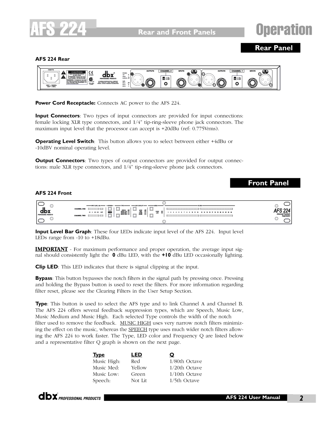
AFS 224 Rear
Power Cord Receptacle: Connects AC power to the AFS 224.
Input Connectors: Two types of input connectors are provided for input connections: female locking XLR type connectors, and 1/4”
Operating Level Switch: This button allows you to select between either +4dBu or
Output Connectors: Two types of output connectors are provided for output connec-
tions: male XLR type connectors, and 1/4”
Front Panel
AFS 224 Front
Input Level Bar Graph: These four LEDs indicate input level of the AFS 224. Input level LEDs range from
IMPORTANT - For maximum performance and proper operation, the average input sig- nal should consistently light the 0 dBu LED, with the +10 dBu LED occasionally lighting.
Clip LED: This LED indicates that there is signal clipping at the input.
Bypass: This button bypasses the notch filters in the signal path by pressing once. Pressing and holding the Bypass button is used to reset the filters. For more information regarding filter reset, please see the Clearing Filters in the User Setup Section.
Type: This button is used to select the AFS type and to link Channel A and Channel B. The AFS 224 offers several feedback suppression types, which are Speech, Music Low, Music Medium and Music High. Each selected Type controls the width of the notch filter used to remove the feedback. MUSIC HIGH uses very narrow notch filters minimiz- ing the effect on the music, whereas the SPEECH type uses much wider notch filters allow- ing the AFS 224 to work faster. The Type, LED color and Frequency Q are listed below and a representative filter Q graph is shown on the next page.
Type | LED | Q |
Music High: | Red | 1/80th Octave |
Music Med: | Yellow | 1/20th Octave |
Music Low: | Green | 1/10th Octave |
Speech: | Not Lit | 1/5th Octave |
®
AFS 224 User Manual | 2 |
|
|
