W . d e l l . c o m s u p p o r t . d e l l . c o m
Service tag Floppy drive light Power light Power button
Network adapter connector
September WD492
Contents
Advanced Troubleshooting
Resolving Software and Hardware Incompatibilities
Using Microsoft Windows XP System Restore
Appendix
Finding Information
What Are You Looking For? Find It Here Warranty information
Finding Information
When you use
Use the Service Tag to
Service Code to direct
Order status, warranty, and repair information
Connecting a USB Printer
Setting Up a Printer
Setting Up and Using Your Computer
Printer Cable
USB connector on computer
Connecting a Parallel Printer
Connecting to a Network Adapter
Setting Up a Home and Office Network
Click Checklist for creating a network
Connecting to the Internet
Network Setup Wizard
If you have a CD, click Use the CD I got from an ISP
Setting Up Your Internet Connection
Click Connect to the Internet
Playing CDs and DVDs
DVD player includes the following basic buttons
Adjusting the Volume
How to Copy a CD or DVD
Adjusting the Picture
Copying CDs and DVDs
800 by 600 pixels
Media Type Read Write Rewritable
Using Blank CDs and DVDs
Click Hardware and click Device Manager
Hyper-Threading
Helpful Tips
Battery Problems
Troubleshooting Tips
Drive Problems
Solving Problems
Problems writing to a CD/DVD-RW drive
CD and DVD drive problems
Hard drive problems
Mail, Modem, and Internet Problems
Use these characters in filenames
Error Messages
Ieee 1394 Device Problems
Lockups and Software Problems
Keyboard Problems
Computer does not start up
Computer stops responding
Program crashes repeatedly
Program stops responding
Program is designed for an earlier Windows operating system
Solid blue screen appears
Other software problems
Memory Problems
Mouse Problems
Power Problems
Network Problems
Printer Problems
Scanner Problems
No sound from speakers
Sound and Speaker Problems
If the screen is blank
Video and Monitor Problems
No sound from headphones
If the screen is difficult to read
Solving Problems
Light Pattern Problem Description Suggested Resolution
Diagnostic Lights
If the problem persists, contact Dell see
Advanced Troubleshooting
Remove the card, reinstall it see
Problem Description Suggested Resolution
If the problem still exists, install a
If the problem persists or
Restarting the computer see
Determine if a conflict exists by
See
Ensure that the cables are properly
Option Function
Dell Diagnostics
Dell Diagnostics Main Menu
Tab Function
Reinstalling Drivers
What Is a Driver?
Drivers
Identifying Drivers
Restoring Your Operating System
Using Windows XP Device Driver Rollback
Manually Reinstalling Drivers
Restoring the Computer to an Earlier Operating State
Using Microsoft Windows XP System Restore
Creating a Restore Point
Enabling System Restore
Using Dell PC Restore by Symantec
Undoing the Last System Restore
Removing Dell PC Restore
Reinstalling Windows XP
Using the Operating System CD
Before You Begin
Dell Operating System CD
Resolving Software and Hardware Incompatibilities
Before You Begin
Removing and Installing Parts
Recommended Tools
Turning Off Your Computer
Before Working Inside Your Computer
Front View
Front and Back View of the Computer
Back View
Cable from your monitor into the blue connector
Modem connector
Computer cover Cover latch Back of computer
Removing the Computer Cover
Inside View of Your Computer
Connector J6J1 J7J2 Main power connector J3J1
Floppy drive connector IDE drive connector CD/DVD drive
Internal speaker LS9J1 Password jumper
CD/DVD audio connector J9C1
DDR Memory Overview
Memory Installation Guidelines
Memory
Installing Memory
Crossbar
Securing clips Connector
Notch
PCI Cards
Installing a PCI Card
Cards
Card Card cutout
Securing screw Filler bracket
Not fully seated card Fully seated card Bracket
Removing a PCI Card
Front Panel
Side hinges Front panel Top tab
Removing the Front Panel
Tabs Insert
Removing the Front-Panel Insert
Side hinges Front panel
Drives
Reattaching the Front Panel
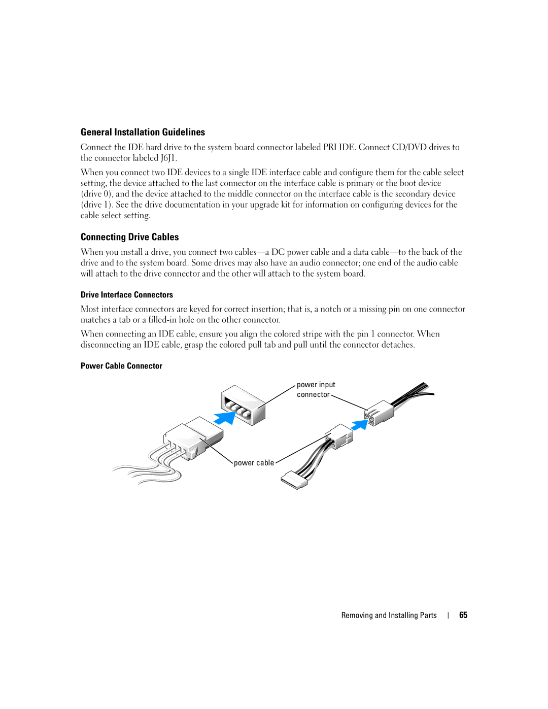
Connecting Drive Cables
General Installation Guidelines
Drive Interface Connectors
Power Cable Connector
Removing a Hard Drive
Power cable Data cable
Hard Drive
Small bracket tabs Drive bracket Hard drive Screws
Hard drive Bracket tabs Drive bracket
Installing a Hard Drive
Removing and Installing Parts
Removing a Floppy Drive
Power cable Data cable Removing and Installing Parts
Floppy Drive
Top bracket screw Drive bracket Floppy drive
Installing a Floppy Drive
Power cable Data cable
Removing a CD/DVD Drive
Data cable Power cable
CD/DVD Drive
Installing a CD/DVD Drive
Drive Alignment screws
Adding a Second CD or DVD Drive
Drive Securing screw
Battery
Replacing the Computer Cover
Battery Battery socket Tab
Specifications
Connectors
Connectors Three Connector size Pins
Video
Audio
Power
Connectors PS/2 keyboard and mouse
Information Backup battery
Wattage
Overview
System Setup
System Setup Screens
Entering System Setup
System
System Setup Options
Disabled Hyper-Threading is Off
IDE CD-ROM Device not installed
Enabled Hyper-Threading is On
Life of the processor and void the warranty
To Off, AT, PS/2, EPP, or ECP
COM3
Auto, Read Only, or Off
Up from Hibernate or Off
Its performance is not affected
Enabled or Disabled
Changing Boot Sequence for the Current Boot
Boot Sequence
Option Settings
Changing Boot Sequence for Future Boots
Clearing Forgotten Passwords
Computer, Keyboard, and Monitor
Cleaning Your Computer
Mouse
Floppy Drive
CDs and DVDs
Definition of Dell-Installed Software and Peripherals
Dell Technical Support Policy U.S. Only
Class a Class B
FCC Notices U.S. Only
Definition of Third-Party Software and Peripherals
FCC Identification Information
Contacting Dell
Argentina Buenos Aires
Antigua and Barbuda
Aruba
Toll-free
0660
0820 240 530
Bahamas
Barbados
Chile Santiago
866 440
Cayman Islands
592 818
818
Colombia
980-9-15-3978
Denmark Copenhagen Website support.euro.dell.com
02 2186 27
7023
3287
100
101
102
103
104
105
106
107
108
109
110
111
112
Index
113
114
115
116
USB