2.Spanning the bottom and top chassis covers and placed in the back left corner
3.Spanning the chassis screw on the bottom left corner
4.Spanning the chassis screw on the bottom right corner
3.2.3.2To detect access to restricted ports
5.Spanning the serial port
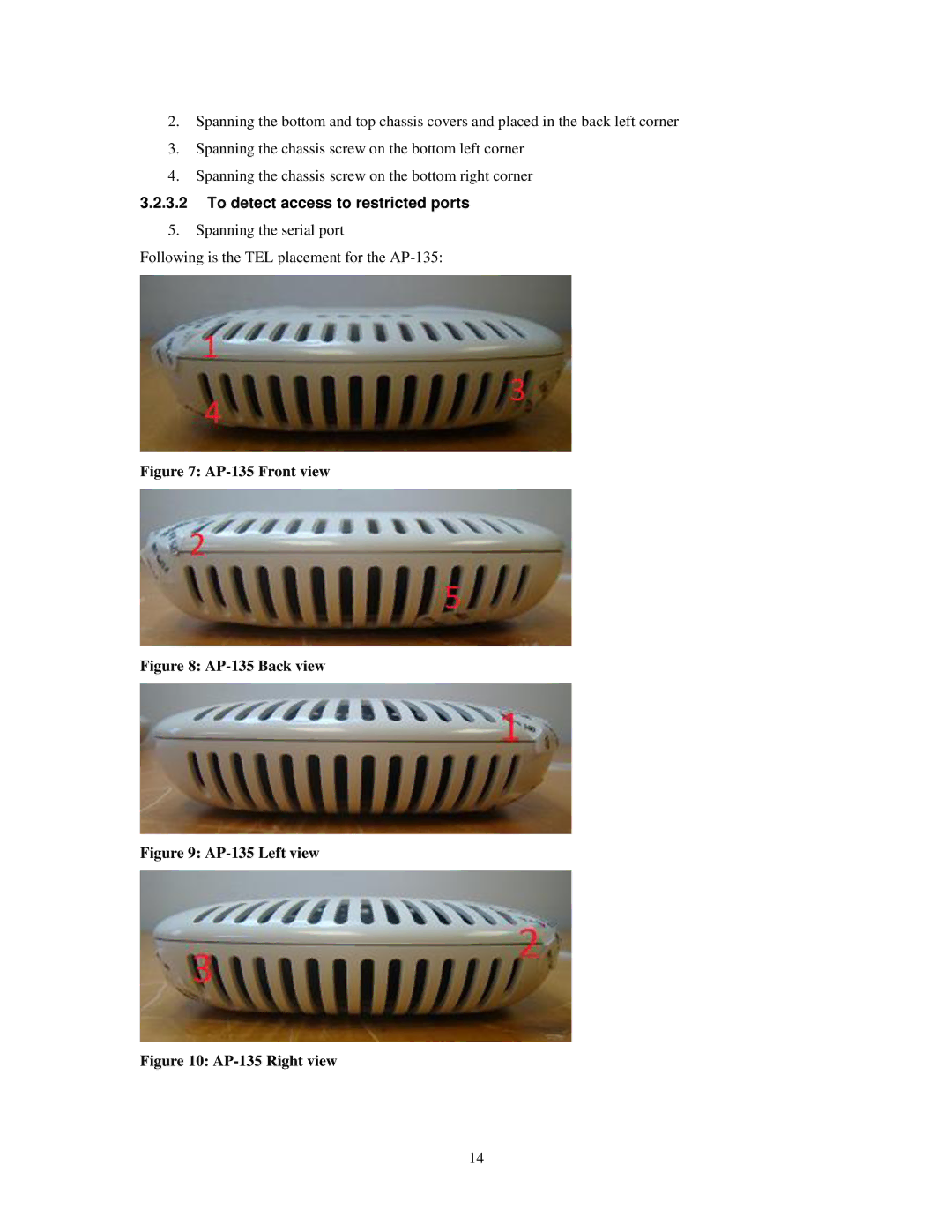
Following is the TEL placement for the
Figure 7: AP-135 Front view
Figure 8: AP-135 Back view
Figure 9: AP-135 Left view
Figure 10: AP-135 Right view
14