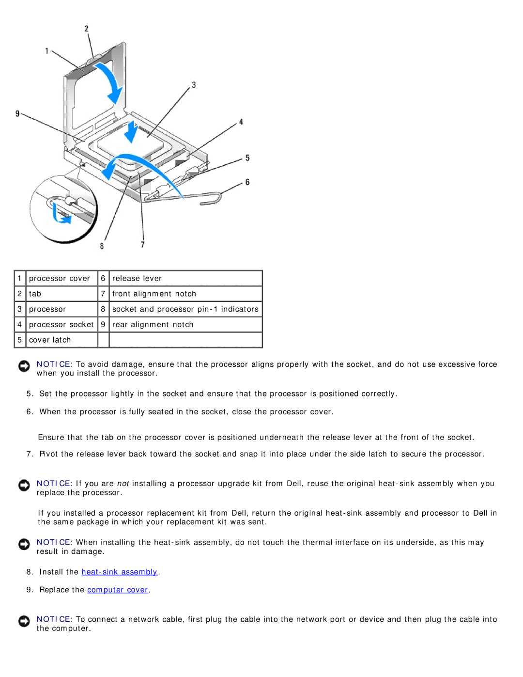
1 | processor cover | 6 | release lever |
2 | tab | 7 | front alignment notch |
3 | processor | 8 | socket and processor |
4 | processor socket | 9 | rear alignment notch |
5 | cover latch |
|
|
NOTICE: To avoid damage, ensure that the processor aligns properly with the socket, and do not use excessive force when you install the processor.
5.Set the processor lightly in the socket and ensure that the processor is positioned correctly.
6.When the processor is fully seated in the socket, close the processor cover.
Ensure that the tab on the processor cover is positioned underneath the release lever at the front of the socket.
7. Pivot the release lever back toward the socket and snap it into place under the side latch to secure the processor.
NOTICE: If you are not installing a processor upgrade kit from Dell, reuse the original
If you installed a processor replacement kit from Dell, return the original
NOTICE: When installing the
8.Install the heat-sink assembly.
9.Replace the computer cover.
NOTICE: To connect a network cable, first plug the cable into the network port or device and then plug the cable into the computer.