Manuals
/
Dell
/
Household Appliance
/
Fan
Dell
DCSM
manual
Power Supply DC Connector Pin Assignments
Models:
DCSM
1
9
72
72
Download
72 pages
7.23 Kb
6
7
8
9
10
11
12
13
Troubleshooting
Specification
Install
Password
Maintenance
Dell Diagnostics Main Menu
System Setup
DC FDD Connector P7
Heat-Sink Assembly
Jumper Settings
Page 9
Image 9
Power Supply DC Connector Pin Assignments
Page 8
Page 10
Page 9
Image 9
Page 8
Page 10
Contents
Model Dcsm August 2006 Rev. A01
Getting Started
Before You Begin
Recommended Tools
Turning Off Your Computer
Remove the computer cover Back to Contents
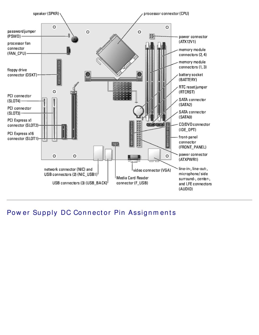
Front View of the Computer
Technical Overview
Back View of the Computer
Page
Inside View of Your Computer
System Board Components
Power Supply DC Connector Pin Assignments
Pin Number Signal Name AWG Wire
DC Main Power Connector P1
DC Peripheral Connectors P3 and P5
DC Processor Power Connector P2
DC FDD Connector P7
Pin Number Signal Name 18-AWG Wire
DC Peripheral Connectors P8 and P9
Processor
Specifications
Memory
Computer Information
Audio
Connectors
Expansion Bus
Drives
Controls and Lights
Power
Environmental
Physical
Removing the Computer Cover
Removing and Installing Parts
Memory
DDR2 Memory Overview
Removing Memory
Addressing Memory With 4-GB Configurations
Installing Memory
Replace the computer cover
Cards
PCI Cards
Installing a PCI Card
Page
Removing a PCI Card
PCI Express Cards
Installing a PCI Express Card
Page
Page
Removing a PCI Express Card
Removing the Drive Panel
Drive Panel
Removing the Drive-Panel Insert
Replacing the Drive-Panel Insert
Front Panel
Replacing the Drive Panel
Removing the Front Panel
Drives
IDE Drive Addressing
Connecting and Disconnecting Drive Interface Cables
Hard Drive
Power Cable Connector
Removing a Hard Drive
Installing a Hard Drive
Adding a Second Hard Drive
Removing a Floppy Drive
Floppy Drive
Installing a Floppy Drive
Replace the computer cover
Removing a Media Card Reader
Media Card Reader Optional
Installing a Media Card Reader
Page
Removing a CD/DVD Drive
CD/DVD Drive
Installing a CD/DVD Drive
Replace the computer cover
Removing the Heat-Sink Assembly
Heat-Sink Assembly
Removing the Processor
Processor
Installing the Processor
Install the heat-sink assembly Replace the computer cover
Removing the Fan Assembly
Fan Assembly
Removing the Front I/O Panel
Front I/O Panel
Jumper Setting Description
Jumper Settings
Password features are enabled
System Board
Removing the System Board
Remove the heat-sink assembly and processor
Replacing the System Board
Power Supply
Removing the Power Supply
Replacing the Power Supply
Replacing the Computer Cover
Dell Diagnostics
Troubleshooting
When to Use the Dell Diagnostics
Starting the Dell Diagnostics From Your Hard Drive
Dell Diagnostics Main Menu
Option Function
Tab Function
Power Light Problem Description
Suggested Resolution
System Lights
Light Pattern Problem Description Suggested Resolution
Diagnostic Lights
Beep Codes
Entering System Setup
System Setup
System Setup Screens
Overview
System
System Setup Options
RAID
Off
Auto Power Time
Maintenance
Boot Sequence
Option Settings
Changing Boot Sequence for the Current Boot
Changing Boot Sequence for Future Boots
Clearing Forgotten Passwords
Clearing Cmos Settings
Top
Page
Image
Contents