8
2 Installation and Basic Operation
2.1Switch Platform Hardware Overview
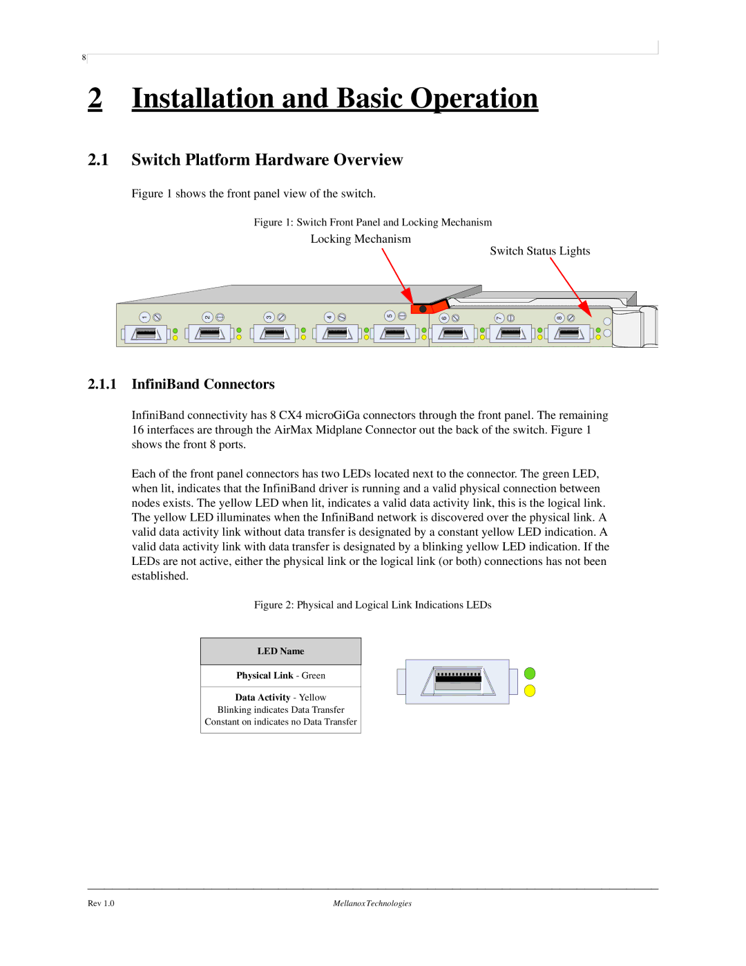
Figure 1 shows the front panel view of the switch.
Figure 1: Switch Front Panel and Locking Mechanism
Locking Mechanism
Switch Status Lights
1 | 2 | 3 | 4 | 5 | 6 | 7 | 8 |
2.1.1InfiniBand Connectors
InfiniBand connectivity has 8 CX4 microGiGa connectors through the front panel. The remaining 16 interfaces are through the AirMax Midplane Connector out the back of the switch. Figure 1 shows the front 8 ports.
Each of the front panel connectors has two LEDs located next to the connector. The green LED, when lit, indicates that the InfiniBand driver is running and a valid physical connection between nodes exists. The yellow LED when lit, indicates a valid data activity link, this is the logical link. The yellow LED illuminates when the InfiniBand network is discovered over the physical link. A valid data activity link without data transfer is designated by a constant yellow LED indication. A valid data activity link with data transfer is designated by a blinking yellow LED indication. If the LEDs are not active, either the physical link or the logical link (or both) connections has not been established.
Figure 2: Physical and Logical Link Indications LEDs
LED Name
Physical Link - Green
Data Activity - Yellow
Blinking indicates Data Transfer
Constant on indicates no Data Transfer
Rev 1.0 | Mellanox Technologies |