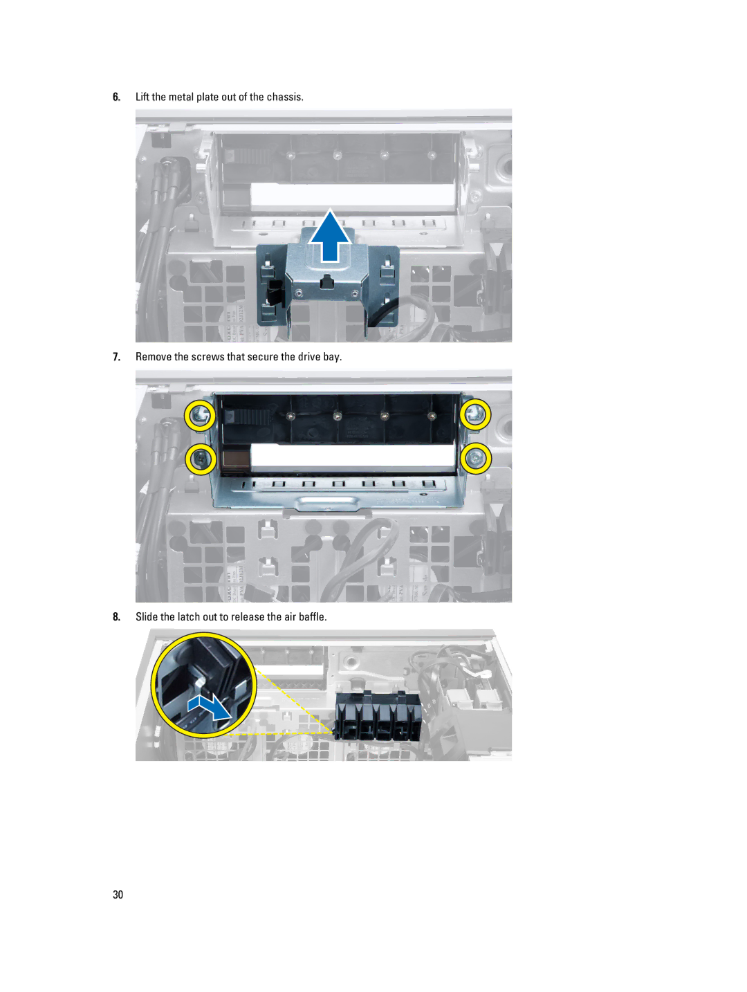
Manuals
/
Dell
/
Computer Equipment
/
Personal Computer
Dell
T5610 Lift the metal plate out of the chassis, Remove the screws that secure the drive bay
Models:
T5610
1
30
73
73
Download
73 pages
16.47 Kb
27
28
29
30
31
32
33
34
<
>
Troubleshooting
Specification
Install
Error codes
Dell Reliable Memory Technology RMT has discovered and isolated errors in system memory. You may continue to work. Memory module replacement is recommended. Please refer to the RMT Event log screen in BIOS setup for specific DIMM information
System Configuration
PCIe x16 slot wired as 4. PCIe x1 slot 6. PCIe x16 slot wired as
solid amber light - the computer does not start, indicating a problem
Diagnostics
System Setup
Page 30
Image 30
6.
Lift the metal plate out of the chassis.
7.
Remove the screws that secure the drive bay.
8.
Slide the latch out to release the air baffle.
30
Page 29
Page 31
Page 30
Image 30
Page 29
Page 31
Contents
Dell Precision Workstation T5610 Owners Manual
Regulatory Model D01T Regulatory Type D01T003
Notes, Cautions, and Warnings
Contents
2 Removing and Installing Components
1 Working on Your Computer
6 Troubleshooting Your Computer
4 System Setup
5 Diagnostics
7 Technical Specifications
Working on Your Computer
Before Working Inside Your Computer
Turning Off Your Computer
After Working Inside Your Computer
Page
Page
Removing and Installing Components
Recommended Tools
Removing the Power Supply Unit PSU
1. Follow the procedures in Before Working Inside Your Computer
System Overview
4. Hold the handle bar to slide the PSU out of the computer
Installing the Power Supply Unit PSU
2. Follow the procedures in After Working Inside Your Computer
1. Hold the PSU handle and slide the PSU into the computer
2. Lay down the computer on its side with the latch facing up
Removing the Cover
1. Follow the procedures in Before Working Inside Your Computer
3. Lift up the cover-release latch
Removing the Front Bezel
Installing the Cover
3. Follow the procedures in After Working Inside Your Computer
1. Follow the procedures in Before Working Inside Your Computer
Removing the Optical Drive
Installing the Front Bezel
4. Follow the procedures in After Working Inside Your Computer
1. Follow the procedures in Before Working Inside Your Computer
4. Unthread the cables from the latches
6. Press down on the latch and lift up the cables
7. Lift up the release latch on top of the optical-drive cage
Removing the Hard Drive
Installing the Optical Drive
6. Follow the procedures in After Working Inside Your Computer
1. Follow the procedures in Before Working Inside Your Computer
Removing the Thermal Sensor
Installing the Hard Drive
1. Follow the procedures in Before Working On Your Computer
6. Follow the procedures in After Working Inside Your Computer
Installing the Thermal Sensor
4. Follow the procedures in After Working Inside Your Computer
2. Remove a. cover b. front bezel
Removing the Input/Output I/O Panel
1. Follow the procedures in Before Working On Your Computer
3. Remove the screws that secure the USB 3.0 module to the I/O panel
Installing the Input/Output I/O Panel
7. Follow the procedures in After Working Inside Your Computer
Removing the Memory
Installing the Air Tunnel
Removing the Air Tunnel
1. Follow the procedures in Before Working On Your Computer
Installing the Coin-Cell Battery
Installing the Memory
Removing the Coin-Cell Battery
4. Follow the procedures in After Working Inside Your Computer
2. Remove the cover
Removing the Heatsink
1. Follow the procedures in Before Working Inside Your Computer
3. Disconnect the heatsink cable from the system board
Installing the Heatsink
5. Follow the procedures in After Working Inside Your Computer
Removing the Heatsink Fan
1. Slide the heatsink fan into heatsink assembly
Installing the Heatsink Fan
4. Slide the heatsink fan from the heatsink assembly
3. Install a. heatsink b. cover
Removing the Processor
1. Follow the procedures in Before Working Inside Your Computer
6. Follow the procedures in After Working Inside Your Computer
Installing the Processor
Removing the System Fan
1. Follow the procedures in Before Working Inside Your Computer
4. Remove the screw that secures the metal plate to the system fan
5. Press the latches on either side of the metal plate to release it
6. Lift the metal plate out of the chassis
7. Remove the screws that secure the drive bay
8. Slide the latch out to release the air baffle
9. Remove the air baffle out of the computer
10. Remove the PSU cable from the clips
11. Disconnect the system-fan cables from the system board
CAUTION Using excessive force may damage the grommets
Removing the PSU Card
Installing the System Fan
11. Follow the procedures in After Working Inside Your Computer
1. Follow the procedures in Before Working On Your Computer
5. Disconnect the power cables from the system board
3. Slide the baffle cover from its slot towards the front
4. Remove the baffle cover from the computer
6. Follow the procedures in After Working Inside Your Computer
Installing the PSU Card
Removing the Speaker
1. Follow the procedures in Before Working On Your Computer
4. Follow the procedures in After Working Inside Your Computer
Installing the Speaker
2. Connect the speaker cable to the system board 3. Install the cover
3. Disconnect the speaker cable from the system board
2. Remove a. cover b. coin-cell battery c. PCI card d. memory modules
Removing the System Board
1. Follow the procedures in Before Working Inside Your Computer
e. thermal sensor f. air tunnel if available g. heatsink fan
4. Disconnect the cables connected to the system board
5. Remove the screws that secure the system board
7. Lift the system board away from the chassis
Installing the System Board
6. Slide the system board towards the system-fan assembly
2. Tighten the screws to secure the system board to the chassis
m. thermal sensor n. cover o. power supply unit PSU
System Board Components
4. Install a. processor b. memory modules c. coin-cell battery
5. Follow the procedures in After Working Inside Your Computer
15. hard-drive HDD1 fan connector 17. DIMM slots 19. DIMM connectors
7. USB 3.0 front-panel connector
11. processor socket 13. front-panel audio connector
21. PSWD jumper 23. system fan 3 connector
Page
Power Supply Unit PSU Lock
Additional Information
Memory Module Guidelines
Page
System Setup
Boot Sequence
Navigation Keys
System Setup Options
Table 3. System Configuration
NOTE If the hard drives are connected to a RAID controller card
Table 4. Video
Table 5. Security
Table 6. Secure Boot
Table 7. Performance
Default Setting Enable Hardware Prefetch
Default Setting Enable Dell Reliable Memory
Table 9. POST Behavior
Table 10. Virtualization Support
Updating the BIOS
System and Setup Password
Assigning a System Password and Setup Password
1. Follow the procedures in Before Working Inside Your Computer
Deleting or Changing an Existing System and/or Setup Password
Disabling a System Password
11. Follow the procedures in After Working Inside Your Computer
Page
Diagnostics
Enhanced Pre-Boot System Assessment ePSA Diagnostics
Page
Troubleshooting Your Computer
Diagnostic LEDs
A possible graphics card failure has occurred
Error Messages
Errors That Halt Your Computer Completely
Table 15. Errors that do not halt your computer
Errors That Do Not Halt Your Computer
Errors That Soft Halt Your Computer
Table 16. - Errors that soft halt your computer
Dell Reliable Memory Technology RMT has discovered and isolated errors in system memory. You may continue to work. Memory module replacement is recommended. Please refer to the RMT Event log screen in BIOS setup for specific DIMM information
Page
Table 18. System Information
Technical Specifications
Table 17. Processor
Table 19. Memory
Table 22. Network
Table 20. Video
Table 21. Audio
Table 23. Expansion Interfaces
Table 25. External Connectors
Table 24. Drives
supports one 5.25-inches SATA device or supports one
Table 26. Internal Connectors
two 164-pin connectors four when optional second processor is
solid amber light - the computer does not start, indicating a problem
blinking amber light - indicates a problem has occurred with the
Table 27. Controls and Lights
4015.3 BTU/Hr at 100 VAC
amber/blinking light - see the service manual for specific diagnostic
Table 28. Power
4365.5 BTU/Hr at 107 VAC
Table 30. Environmental
40 G +/- 5% with pulse duration of 2 msec +/- 10% equivalent to
105 G +/- 5% with pulse duration of 2 msec +/- 10% equivalent to
Page
Contacting Dell
1. Visit dell.com/support