ATTACHING THE MOTOR PULLEY, THE PULLEY GUARD, AND THE DRIVE BELT
1. | Slide the belt and pulley guard bracket (I) Fig. 27, between |
|
|
|
|
|
|
|
| the motor plate (J) and motor mounting plate (K). |
|
|
|
|
|
|
|
2. | Place a 1/4" external tooth lockwasher on 1/4 |
|
|
|
|
|
|
|
| hex head bolt. Insert the bolt (L) Fig. 27 through the hole in |
|
|
|
|
|
|
|
| the belt and pulley guard bracket (I) Fig. 27. |
|
|
|
|
| I |
|
3. | Position the belt and pulley guard bracket (I) Fig. 28, so that |
|
|
|
|
|
| |
|
|
|
|
|
|
| ||
| the motor pulley (K) is centered and through the hole in the |
| L |
|
|
|
| |
|
|
|
|
|
|
| ||
| belt and pulley guard bracket (I) Fig. 28. Tighten the four hex |
|
|
|
|
|
|
|
| nuts (C) Fig. 24 that fasten the motor to the motor mounting |
|
|
|
|
|
|
|
| plate. |
|
|
|
|
|
|
|
4. | Use a straight edge to align the motor pulley with the arbor |
|
|
|
|
|
|
|
| pulley in the saw cabinet. If necessary, adjust the motor |
|
|
|
|
|
|
|
| pulley (K) Fig. 28 in or out on the motor shaft. |
|
|
|
| Fig. 27 | ||
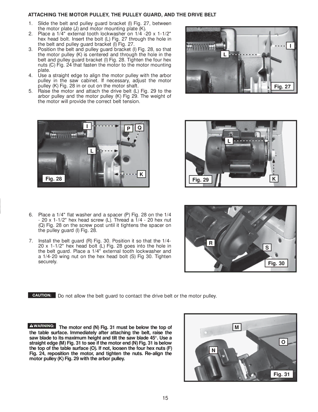
5.Raise the motor and attach the drive belt (L) Fig. 29 to the arbor pulley and the motor pulley (K) Fig 29. The weight of the motor will provide the correct belt tension.
I | P | Q |
| L |
|
Fig. 28 |
| K |
|
|
Fig. 29
L ![]()
![]()
K
6.Place a 1/4" flat washer and a spacer (P) Fig. 28 on the 1/4 - 20 x
(Q) Fig. 28 on the screw post until it tightens the spacer on the pulley guard (I) Fig. 28.
7.Install the belt guard (R) Fig. 30. Position it so that the 1/4- 20 x 1-1/2" hex head bolt (L) Fig. 28 goes into the hole in the belt guard. Place a 1/4" external tooth lockwasher and a 1/4-20 wing nut on the hex head bolt (S) Fig 30. Tighten securely.
R
S
Fig. 30
 Do not allow the belt guard to contact the drive belt or the motor pulley.
|
|
| The motor end (N) Fig. 31 must be below the top of |
|
| M |
|
|
|
|
| ||
|
|
|
|
| ||
the table surface. Immediately after attaching the belt, raise the |
|
|
| |||
saw blade to its maximum height and tilt the saw blade 45°. Use a |
|
|
| |||
straight edge (M) Fig. 31 to see if the motor end (N) Fig. 31 is below |
|
|
| |||
the top of the table surface (O). If not, loosen the four hex nuts (F) |
|
|
| |||
N |
|
| ||||
Fig. 24, reposition the motor, and tighten the nuts. |
| |||||
|
|
| ||||
motor pulley (K) Fig. 29 with the arbor pulley. |
|
|
| |||
O
Fig. 31
15