CONNECTING THE MOTOR CORD TO THE SWITCH ASSEMBLY
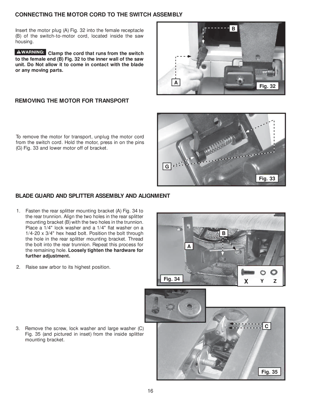
Insert the motor plug (A) Fig. 32 into the female receptacle
(B)of the
![]() Clamp the cord that runs from the switch to the female end (B) Fig. 32 to the inner wall of the saw unit. Do Not allow it to come in contact with the blade or any moving parts.
Clamp the cord that runs from the switch to the female end (B) Fig. 32 to the inner wall of the saw unit. Do Not allow it to come in contact with the blade or any moving parts.
A
![]() B
B
Fig. 32
REMOVING THE MOTOR FOR TRANSPORT
To remove the motor for transport, unplug the motor cord from the switch cord. Hold the motor, press in on the pins
(G) Fig. 33 and lower motor off of bracket.
G |
Fig. 33 |
BLADE GUARD AND SPLITTER ASSEMBLY AND ALIGNMENT
1.Fasten the rear splitter mounting bracket (A) Fig. 34 to the rear trunnion. Align the two holes in the rear splitter mounting bracket (B) with the two holes in the trunnion. Place a 1/4" lock washer and a 1/4" flat washer on a
2.Raise saw arbor to its highest position.
| B |
|
|
| A |
|
|
Fig. 34 | X | Y | Z |
|
3.Remove the screw, lock washer and large washer (C) Fig. 35 (and pictured in inset) from the inside splitter mounting bracket.
![]()
![]() C
C
Fig. 35
16
