ASSEMBLING THE STAND
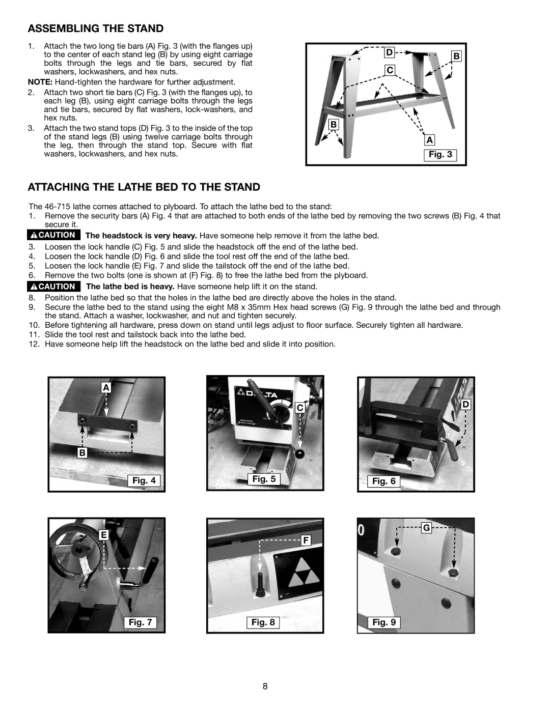
1.Attach the two long tie bars (A) Fig. 3 (with the flanges up) to the center of each stand leg (B) by using eight carriage bolts through the legs and tie bars, secured by flat washers, lockwashers, and hex nuts.
NOTE:
2.Attach two short tie bars (C) Fig. 3 (with the flanges up), to each leg (B), using eight carriage bolts through the legs and tie bars, secured by flat washers,
3.Attach the two stand tops (D) Fig. 3 to the inside of the top of the stand legs (B) using twelve carriage bolts through the leg, then through the stand top. Secure with flat washers, lockwashers, and hex nuts.
D | B |
| |
C |
|
B |
|
| A |
| Fig. 3 |
ATTACHING THE LATHE BED TO THE STAND
The
1.Remove the security bars (A) Fig. 4 that are attached to both ends of the lathe bed by removing the two screws (B) Fig. 4 that secure it.
The headstock is very heavy. Have someone help remove it from the lathe bed.
3.Loosen the lock handle (C) Fig. 5 and slide the headstock off the end of the lathe bed.
4.Loosen the lock handle (D) Fig. 6 and slide the tool rest off the end of the lathe bed.
5.Loosen the lock handle (E) Fig. 7 and slide the tailstock off the end of the lathe bed.
6.Remove the two bolts (one is shown at (F) Fig. 8) to free the lathe bed from the plyboard.
The lathe bed is heavy. Have someone help lift it on the stand.
8.Position the lathe bed so that the holes in the lathe bed are directly above the holes in the stand.
9.Secure the lathe bed to the stand using the eight M8 x 35mm Hex head screws (G) Fig. 9 through the lathe bed and through the stand. Attach a washer, lockwasher, and nut and tighten securely.
10.Before tightening all hardware, press down on stand until legs adjust to floor surface. Securely tighten all hardware.
11.Slide the tool rest and tailstock back into the lathe bed.
12.Have someone help lift the headstock on the lathe bed and slide it into position.
A
B ![]()
![]()
![]()
Fig. 4
E
C
Fig. 5
![]() F
F
D
Fig. 6
![]()
![]()
![]() G
G ![]()
![]()
Fig. 7
Fig. 8
Fig. 9
8