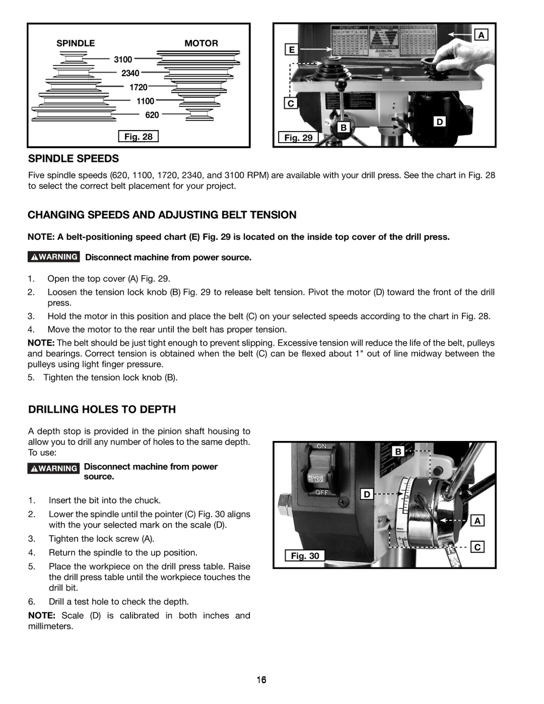
SPINDLE | MOTOR |
3100
2340
1720
1100
620
Fig. 28
E![]()
![]()
C
B
Fig. 29
![]()
![]() A
A
D
SPINDLE SPEEDS
Five spindle speeds (620, 1100, 1720, 2340, and 3100 RPM) are available with your drill press. See the chart in Fig. 28 to select the correct belt placement for your project.
CHANGING SPEEDS AND ADJUSTING BELT TENSION
NOTE: A
Disconnect machine from power source.
1.Open the top cover (A) Fig. 29.
2.Loosen the tension lock knob (B) Fig. 29 to release belt tension. Pivot the motor (D) toward the front of the drill press.
3.Hold the motor in this position and place the belt (C) on your selected speeds according to the chart in Fig. 28.
4.Move the motor to the rear until the belt has proper tension.
NOTE: The belt should be just tight enough to prevent slipping. Excessive tension will reduce the life of the belt, pulleys and bearings. Correct tension is obtained when the belt (C) can be flexed about 1" out of line midway between the pulleys using light finger pressure.
5. Tighten the tension lock knob (B).
DRILLING HOLES TO DEPTH
A depth stop is provided in the pinion shaft housing to allow you to drill any number of holes to the same depth. To use:
Disconnect machine from power source.
1.Insert the bit into the chuck.
2.Lower the spindle until the pointer (C) Fig. 30 aligns with the your selected mark on the scale (D).
3.Tighten the lock screw (A).
4.Return the spindle to the up position.
5.Place the workpiece on the drill press table. Raise the drill press table until the workpiece touches the drill bit.
6.Drill a test hole to check the depth.
NOTE: Scale (D) is calibrated in both inches and millimeters.
Fig. 30
B
D ![]()
![]()
![]()
![]() A
A
C
16