![]()
![]() 3
3 ![]()
![]()
Function/Electrical Specification
Model | DVPPS01 | DVPPS02 | |
Item | |||
|
| ||
Power Input | 100~240 VAC | 100~240 VAC | |
Output Power | 24VDC (±3%), output current: 1A max. | 24VDC (±3%), output current: 2A max. | |
Ripple & Noise | Under | Under | |
Efficiency | 78%~87% Typical at full load | ||
Over Load / Short Circuit Protection | Auto Recovery | ||
Grounding | The diameter of grounding wire cannot be smaller than the wire diameter of terminals L and N | ||
(All PLC units should be grounded directly to the ground pole). | |||
| |||
Operation/Storage Environment | Operation: 0℃~55℃ (Temperature), 50~95% (Humidity), Pollution degree 2; | ||
Storage: | |||
| |||
Agency Approvals | Underwriters Laboratories, Inc.: UL508 Listed (Industrial Control Equipment) | ||
European Community EMC Directive 89/336/EEC and Low Voltage Directive 73/23/EEC | |||
| |||
Weight (g) | 158 | 250 | |
![]()
![]() 4
4 ![]()
![]()
Installation and Wiring
4.1 Mounting Arrangements and Wiring
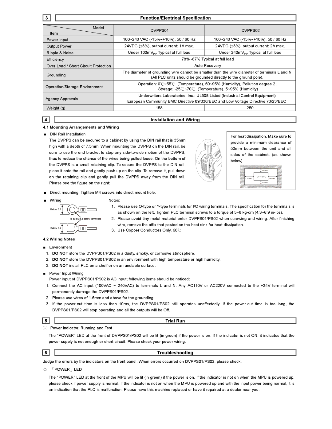
■DIN Rail Installation
The DVPPS can be secured to a cabinet by using the DIN rail that is 35mm high with a depth of 7.5mm. When mounting the DVPPS on the DIN rail, be sure to use the end bracket to stop any
■Direct mounting: Tighten M4 screws into direct mount hole.
For heat dissipation. Make sure to provide a minimum clearance of 50mm between the unit and all sides of the cabinet. (as shown below)
> 50mm
| DVP MPU |
> 50mm | > 50mm |
> 50mm
■Wiring
Below 6.2
Below 6.2
Notes:
1. Please use
To suit M3.5 screw terminals 2. Please avoid tiny metal material enter DVPPS01/PS02 when screwing and wiring. After finishing ![]()
![]()
![]() wire, remove the affix that pasted on the heat sink for heat dissipation.
wire, remove the affix that pasted on the heat sink for heat dissipation.
3. Use Copper Conductors Only, 60℃.
4.2 Wiring Notes
■Environment
1.DO NOT store the DVPPS01/PS02 in a dusty, smoky, or corrosive atmosphere.
2.DO NOT store the DVPPS01/PS02 in an environment with high temperature or high humidity.
3.DO NOT install PLC on a shelf or on an unstable surface.
■Power Input Wiring
Power input of DVPPS01/PS02 is AC input; following items should be noticed:
1.Connect the AC input (100VAC ~ 240VAC) to terminals L and N. Any AC110V or AC220V connected to the +24V terminal will permanently damage the DVPPS01/PS02.
2.Please use wires of 1.6mm and above for the grounding.
3.If the
![]()
![]() 5
5 ![]()
![]()
Trial Run
☼Power indicator, Running and Test
The “POWER” LED at the front of DVPPS01/PS02 will be lit (in green) if the power is on. If the indicator is not ON, it indicates that the power supply is not enough or short circuit. Please check your power wiring.
![]()
![]() 6
6 ![]()
![]()
Troubleshooting
Judge the errors by the indicators on the front panel. When errors occurred on DVPPS01/PS02, please check:
☼「POWER」LED
The “POWER” LED at the front of the MPU will be lit (in green) if the power is on. If the indicator is not on when the MPU is powered up, please check if power supply is normal. If the indicator is not on when the MPU is powered up and with the input power being normal, it is an indication that the PLC is malfunction. Please have this machine replaced or have it repaired at a dealer near you.