ENGLISH
Mode switch setting with daisy chain connection
Set the mode switches of the different components as described on the tables below.
Main unit (DCM-5000) setting
Switch setting
SW1 | SW2 | SW3 | SW4 |
Setting (ID No.)
Disc no. assignment
1
0
0
0
Main unit of a daisy chain
1 ~ 100
Sub unit (DCM-5001) setting
| Switch setting |
|
|
| |
|
|
|
| Setting (ID No.) | Disc no. assignment |
SW1 | SW2 | SW3 | SW4 |
|
|
|
|
|
|
|
|
0 | 0 | 0 | 1 | 1st sub unit in daisy chain | 101 ~ 200 |
|
|
|
|
|
|
0 | 0 | 1 | 0 | 2nd sub unit in daisy chain | 201 ~ 300 |
|
|
|
|
|
|
0 | 0 | 1 | 1 | 3rd sub unit in daisy chain | 301 ~ 400 |
|
|
|
|
|
|
0 | 1 | 0 | 0 | 4th sub unit in daisy chain | 401 ~ 500 |
|
|
|
|
|
|
0 | 1 | 0 | 1 | 5th sub unit in daisy chain | 501 ~ 600 |
|
|
|
|
|
|
*Be sure to make the above settings. Be sure to set the
It is also not possible to skip numbers in the middle. The sub unit connected after the first sub unit must be set to the ID number for the second sub unit.
*If the mode switches are set wrong, the system cannot be operated normaly.
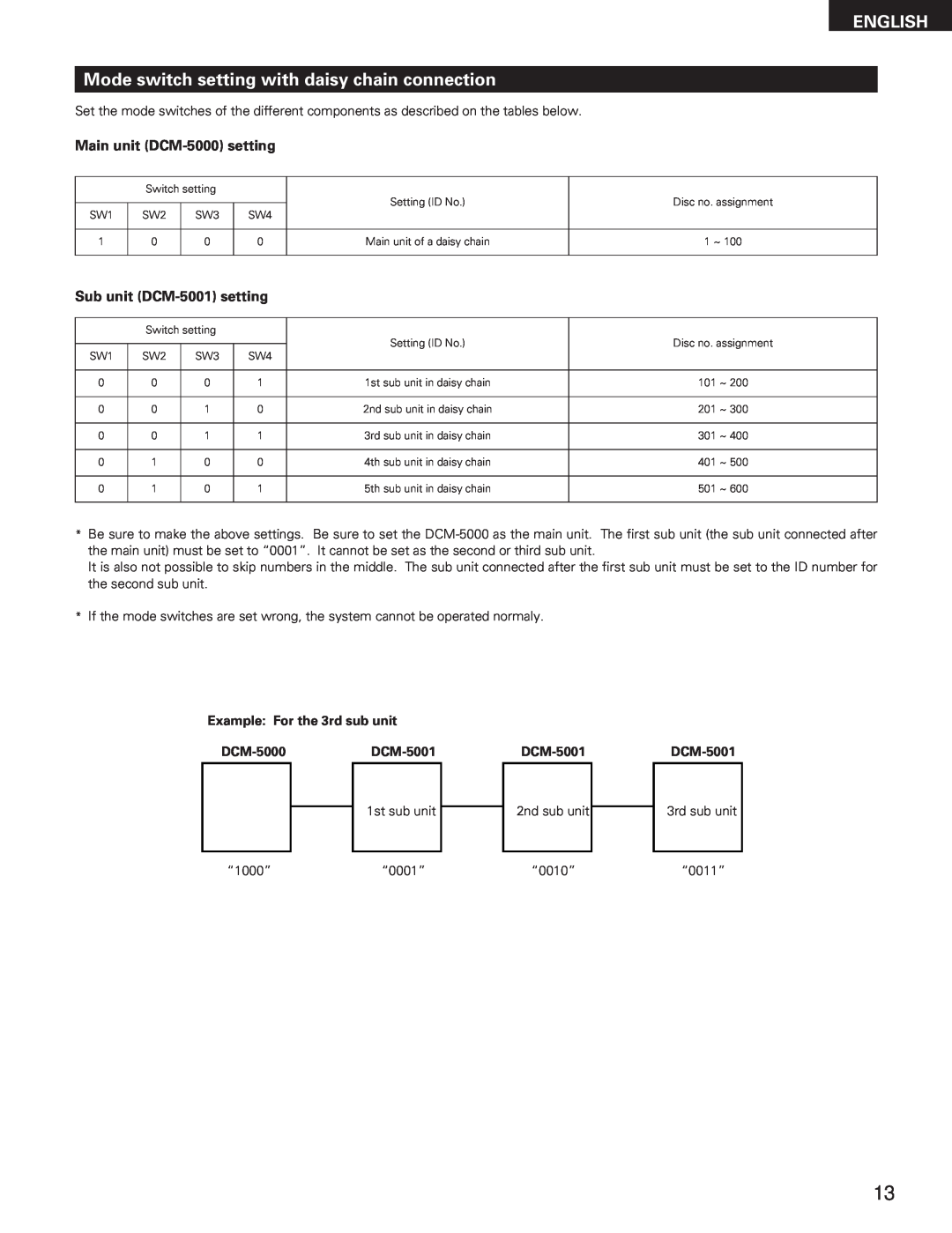
Example: For the 3rd sub unit
1st sub unit
2nd sub unit
3rd sub unit
“1000”“0001”“0010”“0011”
13
