FUELS
![]() WARNING: Use only kero- sene, #1/#2 diesel/fuel oil, JET A
WARNING: Use only kero- sene, #1/#2 diesel/fuel oil, JET A
Use only kerosene, #1/#2 diesel/fuel oil, JET A or
2 diesel fuel may also be used but will result in:
•noticeable odor
•additional fuel filter maintenance
•the need for nontoxic,
Do not use fuels heavier than No. 2 grade or heavy oils such as oil drained from crankcases. These heavy oils will not ignite properly and will contaminate the heater.
IMPORTANT: Use a KEROSENE ONLY (blue) or DIESEL ONLY (yellow) storage container. Be sure storage container is clean. Foreign matter such as rust, dirt or water will cause the ignition control assembly to shut down heater. Foreign matter may also require heaterʼs fuel system to be frequently cleaned.
VENTILATION
![]() WARNING:Provideafreshair opening of at least three square feet (2,800 square cm) for each 100,000 Btu/hr rating. Provide extra fresh air if more heaters are being used. The minimum ventilation requirements must be followed to avoid risks as- sociated with carbon monoxide poisoning. Make certain these requirements are met prior to operating heater.
WARNING:Provideafreshair opening of at least three square feet (2,800 square cm) for each 100,000 Btu/hr rating. Provide extra fresh air if more heaters are being used. The minimum ventilation requirements must be followed to avoid risks as- sociated with carbon monoxide poisoning. Make certain these requirements are met prior to operating heater.
Example: A 200,000 Btu/Hr (58.6 kw) heater requires one of the following:
•a
•a
•two, 30 inch (76.2 cm) windows raised 15 inches (38.1 cm)
THEORY OF OPERATION
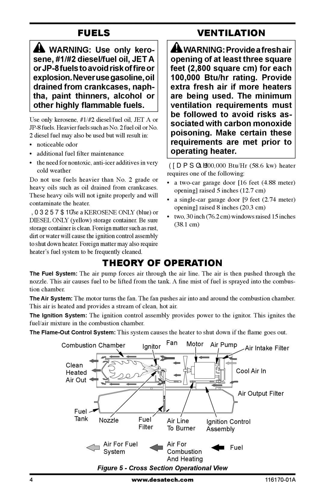
The Fuel System: The air pump forces air through the air line. The air is then pushed through the nozzle. This air causes fuel to be lifted from the tank. A fine mist of fuel is sprayed into the combus- tion chamber.
The Air System: The motor turns the fan. The fan pushes air into and around the combustion chamber. This air is heated and provides a stream of clean, hot air.
The Ignition System: The ignition control assembly provides power to the ignitor. This ignites the fuel/air mixture in the combustion chamber.
The
Combustion Chamber | Ignitor | Fan Motor | Air Pump Air Intake Filter |
Clean |
|
| Cool Air In |
Heated |
|
| |
Air Out |
|
|
|
|
|
| Air Output Filter |
Fuel |
|
|
|
Tank Nozzle | Fuel | Air Line | Ignition Control |
| Filter | To Burner | Assembly |
Air For Fuel |
| Air For | Fuel |
System |
| Combustion | |
|
|
And Heating
Figure 5 - Cross Section Operational View
4 | www.desatech.com |