INSTALLATION
Continued
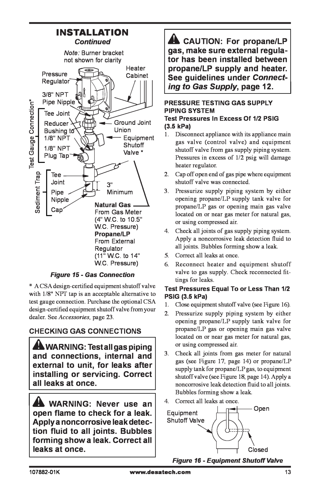
Note: Burner bracket not shown for clarity
Heater
Pressure ![]() Cabinet
Cabinet
Regulator![]()
![]() CAUTION: For propane/LP gas, make sure external regula- tor has been installed between propane/LP supply and heater. See guidelines under Connect-
CAUTION: For propane/LP gas, make sure external regula- tor has been installed between propane/LP supply and heater. See guidelines under Connect-
Test Gauge Connection*![]()
3/8" NPT ![]()
![]()
![]()
![]()
![]()
![]()
![]() Pipe Nipple
Pipe Nipple ![]()
![]()
Tee Joint
Reducer Bushing to 1/8" NPT
1/8" NPT ![]() Plug Tap
Plug Tap![]()
![]()
Ground Joint
Union
![]() Equipment
Equipment
Shutoff
Valve *
ing to Gas Supply, page 12.
PRESSURE TESTING GAS SUPPLY PIPING SYSTEM Test Pressures In Excess Of 1/2 PSIG (3.5 kPa)
1. | Disconnect appliance with its appliance main |
| gas valve (control valve) and equipment |
| shutoff valve from gas supply piping system. |
| Pressures in excess of 1/2 psig will damage |
| heater regulator. |
Trap | Tee |
|
|
| |||
Joint |
|
|
| ||||
| 3" | ||||||
Sediment | Cap |
| |||||
|
| Pipe |
|
|
| Minimum | |
|
|
|
|
| |||
|
|
|
|
| |||
|
| Nipple | Natural Gas | ||||
|
|
|
|
| |||
|
|
|
|
| From Gas Meter | ||
|
|
|
|
| (4" W.C. to 10.5" | ||
|
|
|
|
| W.C. Pressure) | ||
|
|
|
|
| Propane/LP | ||
|
|
|
|
| From External | ||
|
|
|
|
| Regulator | ||
|
|
|
|
| (11" W.C. to 14" | ||
|
|
|
|
| W.C. Pressure) | ||
Figure 15 - Gas Connection
*A CSA
CHECKING GAS CONNECTIONS
![]() WARNING: Test all gas piping and connections, internal and external to unit, for leaks after installing or servicing. Correct all leaks at once.
WARNING: Test all gas piping and connections, internal and external to unit, for leaks after installing or servicing. Correct all leaks at once.
![]() WARNING: Never use an open flame to check for a leak. Apply a noncorrosive leak detec- tion fluid to all joints. Bubbles forming show a leak. Correct all leaks at once.
WARNING: Never use an open flame to check for a leak. Apply a noncorrosive leak detec- tion fluid to all joints. Bubbles forming show a leak. Correct all leaks at once.
2. | Cap off open end of gas pipe where equipment |
| shutoff valve was connected. |
3. | Pressurize supply piping system by either |
| opening propane/LP supply tank valve for |
| propane/LP gas or opening main gas valve |
| located on or near gas meter for natural gas, |
| or using compressed air. |
4. | Check all joints of gas supply piping system. |
| Apply a noncorrosive leak detection fluid to |
| all joints. Bubbles forming show a leak. |
5. | Correct all leaks at once. |
6. | Reconnect heater and equipment shutoff |
| valve to gas supply. Check reconnected fit- |
| tings for leaks. |
Test Pressures Equal To or Less Than 1/2 PSIG (3.5 kPa)
1.Close equipment shutoff valve (see Figure 16).
2.Pressurize supply piping system by either opening propane/LP supply tank valve for propane/LP gas or opening main gas valve located on or near gas meter for natural gas, or using compressed air.
3.Check all joints from gas meter for natural gas (see Figure 17, page 14) or propane/LP supply tank for propane/LP gas, to equipment shutoff valve (see Figure 18, page 14). Apply a noncorrosive leak detection fluid to all joints. Bubbles forming show a leak.
4.Correct all leaks at once.
Equipment | Open |
| |
Shutoff Valve |
|
| Closed |
Figure 16 - Equipment Shutoff Valve | |
www.desatech.com | 13 |