OWNER’S MANUAL
OPERATING
HEATER
FOR YOUR SAFETY
READ BEFORE
LIGHTING
![]() WARNING: If you do not fol- low these instructions exactly, a fire or explosion may result caus- ing property damage, personal injury or loss of life.
WARNING: If you do not fol- low these instructions exactly, a fire or explosion may result caus- ing property damage, personal injury or loss of life.
A. | This appliance has a pilot which must |
| be lighted by hand. When lighting the |
| pilot, follow these instructions exactly. |
B. BEFORE LIGHTING smell all | |
| around the appliance area for gas. Be |
| sure to smell next to the floor because |
| some gas is heavier than air and will |
| settle on the floor. |
| WHAT TO DO IF YOU SMELL |
| GAS |
| • Do not try to light any appliance. |
| • Do not touch any electric switch; do |
| not use any phone in your building. |
| • Immediately call your gas supplier |
| from a neighbor’s phone. Follow |
| the gas supplier’s instructions. |
| • If you cannot reach your gas sup- |
| plier, call the fire department. |
C. Use only your hand to push in or turn | |
| the gas control knob. Never use tools. |
| If the knob will not push in or turn |
| by hand, don’t try to repair it, call a |
| qualified service technician or gas |
| supplier. Force or attempted repair |
| may result in a fire or explosion. |
D. Do not use this appliance if any part | |
| has been under water. Immediately |
| call a qualified service technician to |
| inspect the appliance and to replace |
| any part of the control system and |
| any gas control which has been un- |
LIGHTING
INSTRUCTIONS
![]() WARNING:
WARNING:
•If fireplace has glass doors, never operate this heater with glass doors closed. If you oper- ate heater with doors closed, heat buildup inside fireplace will cause glass to burst. Also if fireplace opening has vents at the bottom, you must open the vents before operating heater.
•You must operate this heater with a fireplace screen in place. Make sure fireplace screen is closed before running heater.
NOTICE: During initial operation of new heater, burning logs will give off a
Note: Homeowners generally prefer to operate their heater with the chimney damper closed. This will put all the heat into the room. However there may be times you will desire the full flames of the Hi heat setting but will find the heat output excessive. You can open the chimney damper (if you have one) fully or partially to release some of the heat.
![]() WARNING: Damper handle will be hot if heater has been running.
WARNING: Damper handle will be hot if heater has been running.
1.STOP! Read the safety information above.
2.Make sure manual shutoff valve is fully open.
3.Set remote selector switch in the OFF position.
![]() WARNING: Burners will come on automatically within one minute when the remote selector switch is in the ON position after the pilot is lit.
WARNING: Burners will come on automatically within one minute when the remote selector switch is in the ON position after the pilot is lit.
4.Press in and turn control knob clock-
wise ![]() to the OFF position.
to the OFF position.
5.Wait five (5) minutes to clear out any gas. Then smell for gas, including near the floor. If you smell gas, STOP! Follow “B” in the safety in- formation above. If you don’t smell gas, go to the next step.
6.Press in and turn control knob coun-
terclockwise ![]() to the PILOT position. Press in control knob for five (5) seconds (see above).
to the PILOT position. Press in control knob for five (5) seconds (see above).
Note: You may be running this heater for the first time after hook- ing up to gas supply. If so, the con- trol knob may need to be pressed in for 30 seconds or more. This will al- low air to bleed from the gas system.
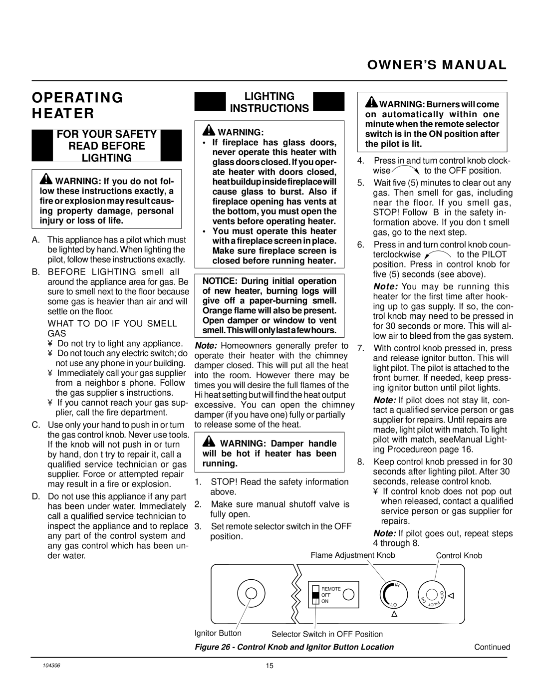
7.With control knob pressed in, press and release ignitor button. This will light pilot. The pilot is attached to the front burner. If needed, keep press- ing ignitor button until pilot lights.
Note: If pilot does not stay lit, con- tact a qualified service person or gas supplier for repairs. Until repairs are made, light pilot with match. To light pilot with match, see Manual Light- ing Procedure on page 16.
8.Keep control knob pressed in for 30 seconds after lighting pilot. After 30 seconds, release control knob.
•If control knob does not pop out when released, contact a qualified service person or gas supplier for repairs.
Note: If pilot goes out, repeat steps 4 through 8.
der water. |
Flame Adjustment Knob | Control Knob |
REMOTE OFF ON
L
IH
O
N O
O
F
F
| P |
I | |
TOL |
|
Ignitor Button | Selector Switch in OFF Position |
|
Figure 26 - Control Knob and Ignitor Button Location | Continued | |
104306 | 15 |
