Manuals
/
Desa
/
Household Appliance
/
Indoor Fireplace
Desa
INSTALLING GA3650T BLOWER ACCESSORY, CGFP28P and CGFP28PT, Installation, Continued
Models:
CGFP28PT
CGFP28P
1
8
34
34
Download
34 pages
26.05 Kb
5
6
7
8
9
10
11
12
Troubleshooting
Specifications
Install
Parts list
Warranty
Maintenance
Log Base Assembly
Manual Lighting Procedure
Cleaning And Maintenance
Safety
Page 8
Image 8
Page 7
Page 9
Page 8
Image 8
Page 7
Page 9
Contents
OWNER’S OPERATION AND INSTALLATION MANUAL
CGFP28P AND CGFP28PT
WHAT TO DO IF YOU SMELL GAS
Do not try to light any appliance
SAFETY INFORMATION
CGFP28P and CGFP28PT
UNVENTED PROPANE/LP GAS FIREPLACE
WARNINGS
UNPACKING
PRODUCT IDENTIFICATION
LOCAL CODES
PRODUCT FEATURES
SAFETY FEATURES
AIR FOR COMBUSTION AND VENTILATION
OPERATION
AIR FOR COMBUSTION AND VENTILATION
Continued
DETERMINING FRESH-AIRFLOW FOR FIREPLACE LOCATION
VENTILATION AIR
CGFP28P and CGFP28PT
UNVENTED PROPANE/LP GAS FIREPLACE
AIR FOR COMBUSTION AND VENTILATION
CHECK GAS TYPE
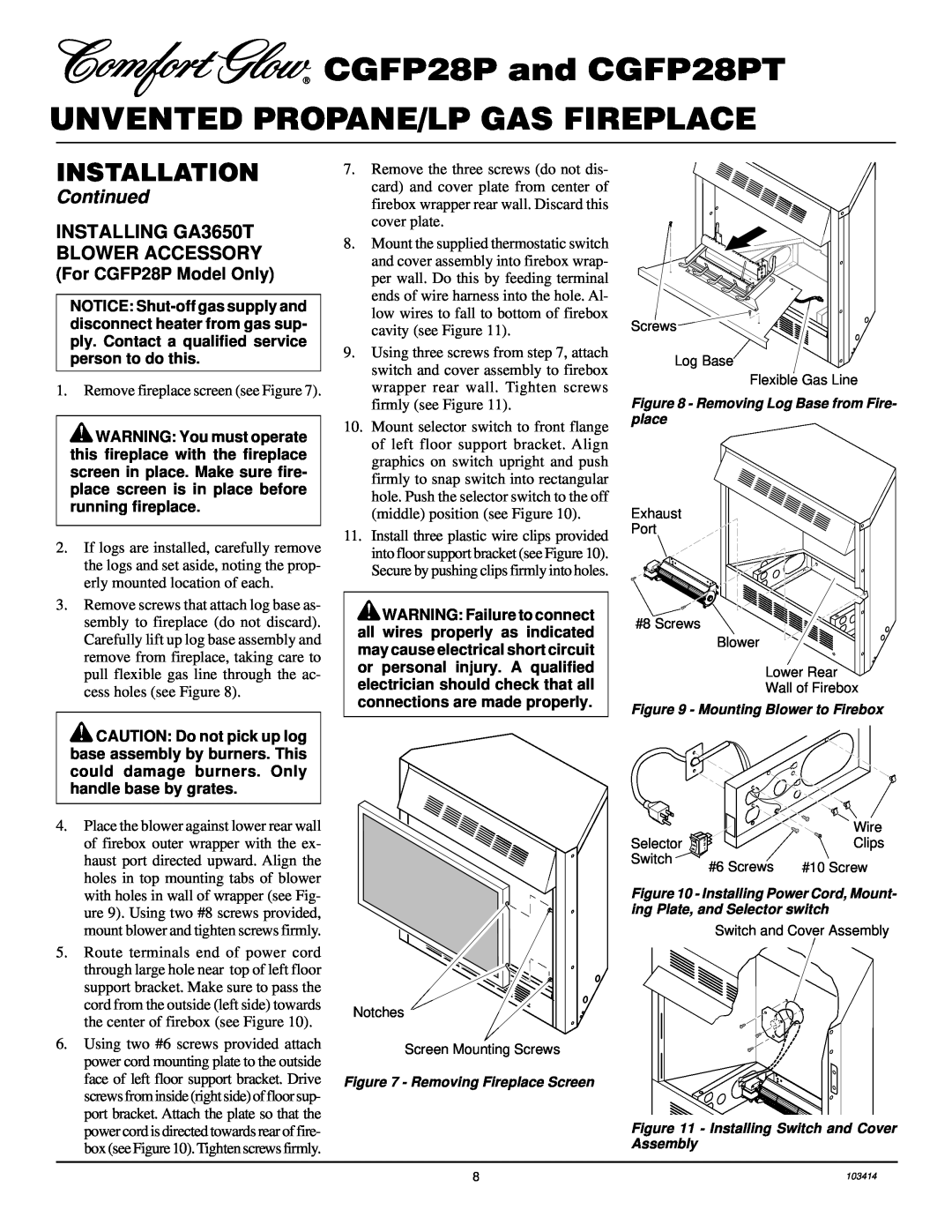
INSTALLATION
ELECTRICAL HOOKUP When Using Optional Blower
INSTALLING GA3650T BLOWER ACCESSORY
INSTALLATION
CGFP28P and CGFP28PT
UNVENTED PROPANE/LP GAS FIREPLACE
OPERATING THE BLOWER
INSTALLATION
If your fireplace system is installed
Continued
INSTALLATION
INSTALLING GA3650T BLOWER ACCESSORY
CGFP28P and CGFP28PT
UNVENTED PROPANE/LP GAS FIREPLACE
INSTALLATION
a. If your fireplace system is installed
Continued
Operating the Blower
INSTALLATION CLEARANCES
CONVENTIONAL FIREPLACE INSTALLATION
INSTALLATION
CGFP28P and CGFP28PT
BUILT-INFIREPLACE INSTALLATION
Check Local Building Codes
INSTALLATION
Continued
INSTALLING GAS PIPING TO FIREPLACE LOCATION
INSTALLATION
CGFP28P and CGFP28PT
UNVENTED PROPANE/LP GAS FIREPLACE
CHECKING GAS CONNECTIONS
Pressure Testing Gas Supply Piping System
INSTALLATION
Pressure Testing Fireplace Gas Connections
CGFP28P and CGFP28PT
UNVENTED PROPANE/LP GAS FIREPLACE
Continued
INSTALLING LOGS
INSTALLATION
FOR YOUR SAFETY READ BEFORE LIGHTING
OPERATING FIREPLACE
LIGHTING INSTRUCTIONS
TO TURN OFF GAS TO APPLIANCE
MANUAL LIGHTING PROCEDURE
THERMOSTAT CONTROL OPERATION
FOR YOUR SAFETY READ BEFORE LIGHTING
OPERATING FIREPLACE
INSPECTING BURNERS
VARIABLE MANUAL CONTROL OPERATION
PILOT FLAME PATTERN
FRONT BURNER FLAME PATTERN
CLEANING AND MAINTENANCE
LOGS
TROUBLESHOOTING
OBSERVED PROBLEM
CGFP28P and CGFP28PT
UNVENTED PROPANE/LP GAS FIREPLACE
TROUBLESHOOTING
Maintenance, page
Continued
Refer to Air for Combustion and Venti
TROUBLESHOOTING
CGFP28P and CGFP28PT
UNVENTED PROPANE/LP GAS FIREPLACE
Continued
SERVICE HINTS
SPECIFICATIONS
TECHNICAL SERVICE
PARTS CENTRALS
ILLUSTRATED PARTS BREAKDOWN
CGFP28P
CGFP28P and CGFP28PT
UNVENTED PROPANE/LP GAS FIREPLACE
PARTS LIST
CGFP28P
PART NUMBER
DESCRIPTION
LOG BASE ASSEMBLY
ILLUSTRATED
PARTS
BREAKDOWN
PARTS LIST
LOG BASE ASSEMBLY THERMOSTAT- CONTROLLED MODEL
CGFP28PT
FIREPLACE
CGFP28P and CGFP28PT
UNVENTED PROPANE/LP GAS FIREPLACE
ILLUSTRATED
FIREPLACE CGFP28P CGFP28PT
PARTS LIST
REPLACEMENT PARTS
ACCESSORIES
PARTS UNDER WARRANTY
PARTS NOT UNDER WARRANTY
Page
WARRANTY INFORMATION
NOT A UPC
Model Serial No Date Purchased
2701 Industrial Drive P.O. Box Bowling Green, KY
Top
Page
Image
Contents