5
UNIT DIMENSIONS
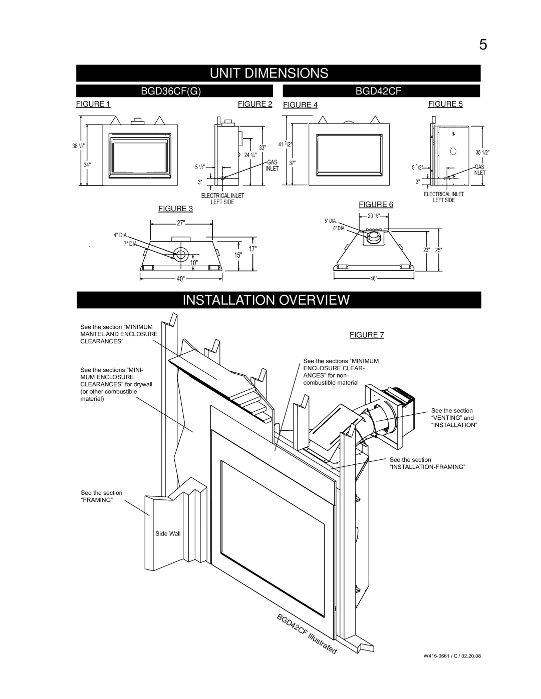
BGD36CF(G)BGD42CF
FIGURE 1 |
|
|
|
|
|
|
|
|
| FIGURE 2 FIGURE 4 | FIGURE 5 | |||||
|
|
|
|
|
|
|
|
|
|
|
|
|
|
|
|
|
|
|
|
|
|
|
|
|
|
|
|
|
|
|
|
|
|
|
|
|
|
|
|
|
|
|
|
|
|
|
|
|
|
|
|
|
|
|
|
|
|
|
|
|
|
|
|
|
|
|
|
|
|
|
|
|
|
|
|
|
|
|
|
|
|
|
|
|
|
|
|
|
|
|
|
|
|
|
|
|
|
|
|
|
|
|
|
|
|
|
|
|
|
|
|
|
|
|
|
|
|
|
|
|
|
|
|
|
|
|
|
|
|
|
|
|
|
|
|
|
|
|
|
|
|
|
|
|
|
|
|
|
|
|
|
|
38 1/2"
34"
| 33" | 41 1/2" |
|
| |
| 24 1/4" |
|
5 1/2" | GAS | 37" |
INLET | ||
3"
ELECTRICAL INLET
5 1/2"
3"
ELECTRICAL INLET
35 1/2"
GAS
INLET
LEFT SIDE
FIGURE 3
![]() 27"
27"![]()
4" DIA.
7" DIA.
FIGURE 6
![]() 20 1/2"
20 1/2"![]()
5" DIA.
8" DIA.
LEFT SIDE
T
17"
15"
10" |
![]() 40"
40" ![]()
![]()
23" 25"
![]() 46"
46"![]()
INSTALLATION OVERVIEW
See the section “MINIMUM MANTEL AND ENCLOSURE CLEARANCES”
See the sections “MINI-
MUM ENCLOSURE CLEARANCES” for drywall (or other combustible material)
See the section “FRAMING”
FIGURE 7
See the sections “MINIMUM ENCLOSURE CLEAR- ANCES” for non- combustible material
See the section “VENTING” and
“INSTALLATION”
See the section
Side Wall