17
BGD42CF VERTICAL TERMINATION
when (HT) < (VT)
Simple venting confi gurations
FIGURE 38
45°
See graph to determine the required vertical rise VT for the required horizontal run HT.
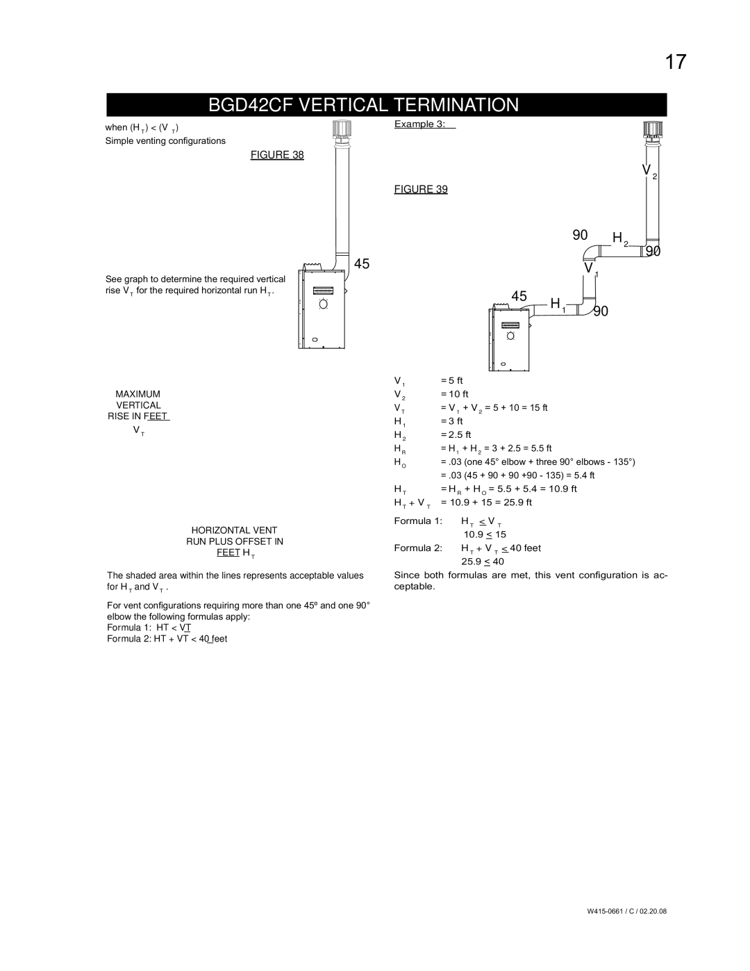
Example 3:
FIGURE 39
90° H2
V1
45° H1 90°
V2
![]()
![]() 90°
90°
MAXIMUM
VERTICAL
RISE IN FEET
VT
HORIZONTAL VENT
RUN PLUS OFFSET IN
FEET HT
The shaded area within the lines represents acceptable values for HT and VT .
For vent confi gurations requiring more than one 45º and one 90° elbow the following formulas apply:
Formula 1: HT < VT
Formula 2: HT + VT < 40 feet
V1 | = 5 ft |
V2 | = 10 ft |
VT | = V1 + V2 = 5 + 10 = 15 ft |
H1 | = 3 ft |
H2 | = 2.5 ft |
HR | = H1 + H2 = 3 + 2.5 = 5.5 ft |
HO | = .03 (one 45° elbow + three 90° elbows - 135°) |
| = .03 (45 + 90 + 90 +90 - 135) = 5.4 ft |
HT | = HR + HO = 5.5 + 5.4 = 10.9 ft |
HT + VT | = 10.9 + 15 = 25.9 ft |
Formula 1: HT < VT 10.9 < 15
Formula 2: HT + VT < 40 feet 25.9 < 40
Since both formulas are met, this vent confi guration is ac- ceptable.