21
USING FLEXIBLE VENT COMPONENTS
THE BGD36CF(G) USES: 4" EXHAUST / 7" AIR INTAKE VENT PIPE WITH A MINIMUM 6" BEND RADIUS
THE BGD42CF USES: 5" EXHAUST / 8" AIR INTAKE VENT PIPE WITH A MINIMUM 8" BEND RADIUS
! | WARNING | VERTICAL AIR TERMINAL INSTALLATION | ||||
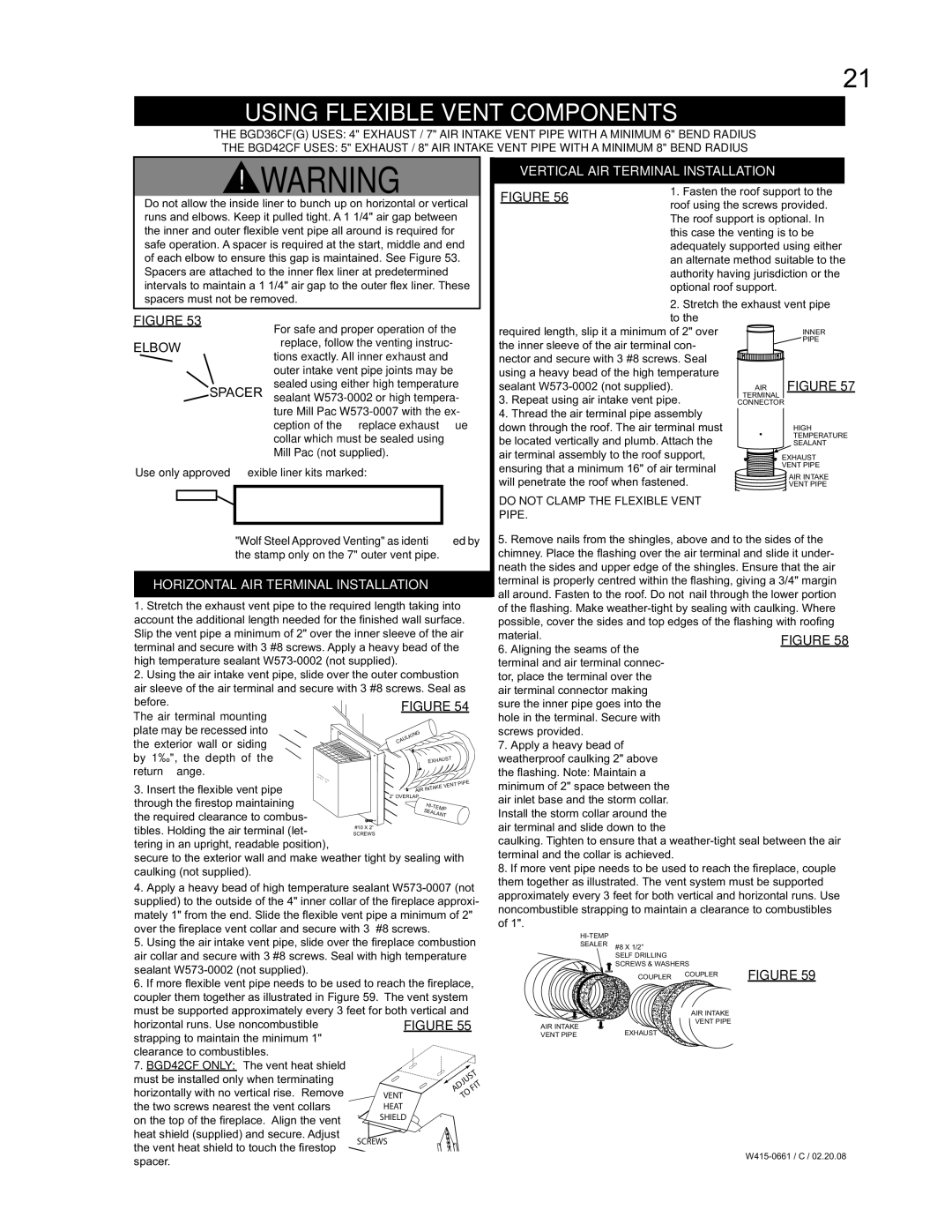
FIGURE 56 | 1. Fasten the roof support to the | |||||
Do not allow the inside liner to bunch up on horizontal or vertical |
| roof using the screws provided. | ||||
runs and elbows. Keep it pulled tight. A 1 1/4" air gap between |
| The roof support is optional. In | ||||
the inner and outer fl exible vent pipe all around is required for |
| this case the venting is to be | ||||
safe operation. A spacer is required at the start, middle and end |
| adequately supported using either | ||||
of each elbow to ensure this gap is maintained. See Figure 53. |
| an alternate method suitable to the | ||||
Spacers are attached to the inner fl ex liner at predetermined |
| authority having jurisdiction or the | ||||
intervals to maintain a 1 1/4" air gap to the outer fl ex liner. These |
| optional roof support. |
| |||
spacers must not be removed. |
| 2. Stretch the exhaust vent pipe | ||||
|
|
|
| |||
FIGURE 53 |
| For safe and proper operation of the |
| to the |
|
|
|
| required length, slip it a minimum of 2" over |
| INNER | ||
ELBOW |
| fireplace, follow the venting instruc- | the inner sleeve of the air terminal con- |
| PIPE | |
|
|
| ||||
|
| tions exactly. All inner exhaust and | nector and secure with 3 #8 screws. Seal |
|
| |
|
| outer intake vent pipe joints may be | using a heavy bead of the high temperature |
| FIGURE 57 | |
SPACER | sealed using either high temperature | sealant | AIR | |||
sealant | 3. Repeat using air intake vent pipe. | TERMINAL |
| |||
|
| CONNECTOR | ||||
|
| ture Mill Pac | 4. Thread the air terminal pipe assembly |
|
| |
|
| ception of the fireplace exhaust flue | down through the roof. The air terminal must |
| HIGH | |
|
| collar which must be sealed using | be located vertically and plumb. Attach the |
| TEMPERATURE | |
|
|
| SEALANT | |||
|
| Mill Pac (not supplied). | air terminal assembly to the roof support, |
| EXHAUST | |
Use only approved flexible liner kits marked: | ensuring that a minimum 16" of air terminal |
| VENT PIPE | |||
| AIR INTAKE | |||||
will penetrate the roof when fastened. |
| |||||
|
|
|
| VENT PIPE | ||
|
|
| DO NOT CLAMP THE FLEXIBLE VENT |
|
| |
|
|
| PIPE. |
|
|
|
"Wolf Steel Approved Venting" as identified by the stamp only on the 7" outer vent pipe.
HORIZONTAL AIR TERMINAL INSTALLATION
1.Stretch the exhaust vent pipe to the required length taking into account the additional length needed for the fi nished wall surface. Slip the vent pipe a minimum of 2" over the inner sleeve of the air terminal and secure with 3 #8 screws. Apply a heavy bead of the high temperature sealant
2.Using the air intake vent pipe, slide over the outer combustion air sleeve of the air terminal and secure with 3 #8 screws. Seal as
before.
The air terminal mounting |
|
|
|
plate may be recessed into |
|
| ING |
the exterior wall or siding |
|
| CAULK |
|
|
| |
by 1½", the depth of the |
|
| ST |
|
| EXHAU | |
return flange. | ATTENT |
|
|
CAUTIONION- | CHAUD |
| |
| - |
| |
3. Insert the fl exible vent pipe | HOT | T PIPE | |
|
| ||
|
| AKE VEN | |
|
| AIR INT | |
|
|
| |
through the fi restop maintaining the required clearance to combus- tibles. Holding the air terminal (let- tering in an upright, readable position),
secure to the exterior wall and make weather tight by sealing with caulking (not supplied).
4.Apply a heavy bead of high temperature sealant
5.Using the air intake vent pipe, slide over the fi replace combustion air collar and secure with 3 #8 screws. Seal with high temperature sealant
6.If more fl exible vent pipe needs to be used to reach the fi replace, coupler them together as illustrated in Figure 59. The vent system must be supported approximately every 3 feet for both vertical and
horizontal runs. Use noncombustible strapping to maintain the minimum 1" clearance to combustibles.
7. BGD42CF ONLY: The vent heat shield |
|
|
|
must be installed only when terminating |
| JUST | |
horizontally with no vertical rise. Remove | VENT | AD | FIT |
TO |
| ||
the two screws nearest the vent collars | HEAT |
|
|
on the top of the fi replace. Align the vent | SHIELD |
|
|
heat shield (supplied) and secure. Adjust |
|
|
|
5.Remove nails from the shingles, above and to the sides of the chimney. Place the flashing over the air terminal and slide it under- neath the sides and upper edge of the shingles. Ensure that the air terminal is properly centred within the fl ashing, giving a 3/4" margin all around. Fasten to the roof. Do not nail through the lower portion of the fl ashing. Make
material.
6. Aligning the seams of the terminal and air terminal connec- tor, place the terminal over the air terminal connector making sure the inner pipe goes into the hole in the terminal. Secure with screws provided.
7. Apply a heavy bead of weatherproof caulking 2" above the fl ashing. Note: Maintain a minimum of 2" space between the air inlet base and the storm collar. Install the storm collar around the air terminal and slide down to the
caulking. Tighten to ensure that a
8. If more vent pipe needs to be used to reach the fi replace, couple them together as illustrated. The vent system must be supported approximately every 3 feet for both vertical and horizontal runs. Use noncombustible strapping to maintain a clearance to combustibles of 1".
SEALER #8 X 1/2”
SELF DRILLING
SCREWS & WASHERS
COUPLER | COUPLER | FIGURE 59 |
|
|
AIR INTAKE
VENT PIPE
AIR INTAKE | EXHAUST |
VENT PIPE |
the vent heat shield to touch the fi restop spacer.
SCREWS