INSTALLATION

Continued

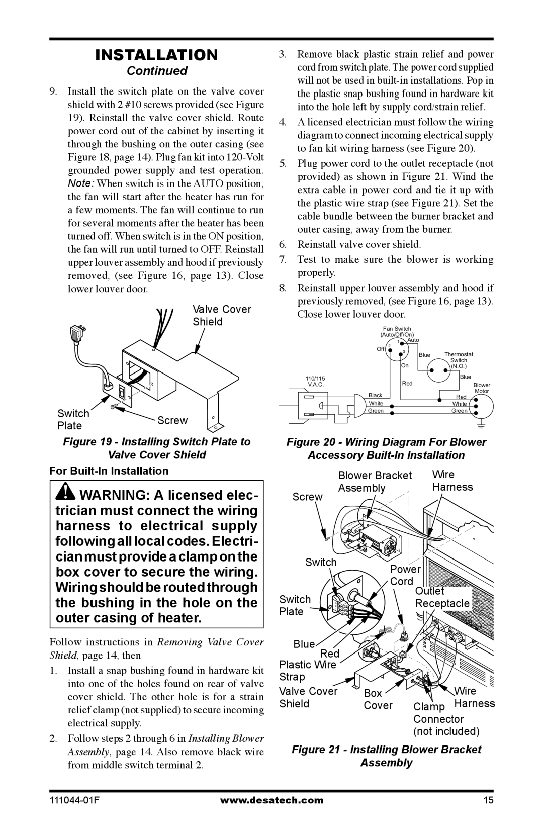
9.Install the switch plate on the valve cover shield with 2 #10 screws provided (see Figure 19). Reinstall the valve cover shield. Route power cord out of the cabinet by inserting it through the bushing on the outer casing (see Figure 18, page 14). Plug fan kit into 120-Volt grounded power supply and test operation. Note: When switch is in the AUTO position, the fan will start after the heater has run for a few moments. The fan will continue to run for several moments after the heater has been turned off. When switch is in the ON position, the fan will run until turned to OFF. Reinstall upper louver assembly and hood if previously removed, (see Figure 16, page 13). Close lower louver door.

Valve Cover

Shield

Switch

PlateScrew

Figure 19 - Installing Switch Plate to

Valve Cover Shield

For Built-In Installation

WARNING: A licensed elec- trician must connect the wiring harness to electrical supply following all local codes. Electri- cian must provide a clamp on the box cover to secure the wiring. Wiring should be routed through the bushing in the hole on the outer casing of heater.

Follow instructions in Removing Valve Cover Shield, page 14, then

1.Install a snap bushing found in hardware kit into one of the holes found on rear of valve cover shield. The other hole is for a strain relief clamp (not supplied) to secure incoming electrical supply.

2.Follow steps 2 through 6 in Installing Blower Assembly, page 14. Also remove black wire from middle switch terminal 2.

3.Remove black plastic strain relief and power cord from switch plate. The power cord supplied will not be used in built-in installations. Pop in the plastic snap bushing found in hardware kit into the hole left by supply cord/strain relief.

4.A licensed electrician must follow the wiring diagram to connect incoming electrical supply to fan kit wiring harness (see Figure 20).

5.Plug power cord to the outlet receptacle (not provided) as shown in Figure 21. Wind the extra cable in power cord and tie it up with the plastic wire strap (see Figure 21). Set the cable bundle between the burner bracket and outer casing, away from the burner.

6.Reinstall valve cover shield.

7.Test to make sure the blower is working properly.

8.Reinstall upper louver assembly and hood if previously removed, (see Figure 16, page 13).

Close lower louver door.

Fan Switch

(Auto/Off/On)

1Auto


Off

2


3

Blue


Thermostat


On


Switch


(N.O.)

110/115


Red


Blue

V.A.C.


Blower


Black


Motor


Red


White


White


Green


Green

Figure 20 - Wiring Diagram For Blower

Accessory Built-In Installation


Blower Bracket

Wire

Screw

Assembly

Harness


Switch

Power


Switch

Cord Outlet


Receptacle

Plate


Blue Red


Plastic Wire


Strap


Valve Cover

Box


Wire

Shield

Cover

Clamp

Harness

Connector (not included)

Figure 21 - Installing Blower Bracket

Assembly

111044-01F

www.desatech.com

15

Page 15
Image 15
Desa CGCFTP, CGCFTN 14, HDCFTN installation manual For Built-In Installation, Close lower louver door

CGCFTP, CGCFTN 14, HDCFTN specifications

Desa HDCFTN, CGCFTP, and CGCFTN 14 represent a significant advancement in the landscape of modern digital architecture. These entities are characterized by their unique blend of features, technologies, and characteristics that cater to various applications and industries.

At the core of these systems is the high-density computing and flexible trading network (HDCFTN) structure, which allows for scalable operations and enhanced processing capabilities. This architecture is designed to efficiently handle large volumes of data transactions, making it ideal for sectors such as finance, telecommunications, and research institutions. By incorporating distributed computing, HDCFTN can optimize resource allocation and significantly reduce latency compared to traditional centralized systems.

CGCFTP, or the Cloud-based Grid Computing for Financial Transactions Platform, serves as a robust framework that integrates real-time data processing and analysis. Its cloud-native design ensures seamless connectivity and scalability, enabling organizations to operate in a flexible environment. The platform utilizes microservices architecture, which allows for independent deployment and scaling of different components, leading to improved performance and resilience.

Meanwhile, CGCFTN 14 focuses on providing end-to-end solutions for trading and financial operations. It incorporates advanced security protocols and compliance features, addressing the increasing regulatory demands prevalent in the financial sector. Utilizing blockchain technology, CGCFTN 14 ensures data integrity and transparency, creating trust among users while minimizing the risk of fraud or misconduct.

The combination of artificial intelligence (AI) and machine learning (ML) within these frameworks enhances predictive analytics and decision-making processes. With algorithms that learn from historical data, organizations can anticipate market trends and adjust their strategies accordingly. The integration of big data analytics further fuels real-time insights, empowering businesses to respond swiftly to market changes.

Moreover, these innovative systems embrace interoperability, connecting with various existing technologies and platforms. This flexibility allows organizations to leverage their current investments while still benefiting from new technological advancements. In summary, Desa HDCFTN, CGCFTP, and CGCFTN 14 exemplify the future of digital infrastructure, characterized by high density, cloud integration, advanced security, and intelligent analytics, driving efficiency and innovation across industries.