CAST IRON STOVE AND B-VENT BURNER SYSTEM INSTALLATION

Checking Gas Connections (Cont.)

Installing Optional Wall Mount Switch - GWMS2

Installing Optional Wall Mounted Thermostat - GWMT1

15

CAST IRON STOVE AND B-VENT BURNER SYSTEM INSTALLATION

Continued

Pressure Testing Burner System Gas

Connections

1.Open equipment shutoff valve (see Figure 31, page 14).

2.Open propane/LP supply tank valve for propane/LP burner system or main gas valve located on or near gas meter for natural gas burner system.

3.Make sure control knob of burner system is in the OFF position.

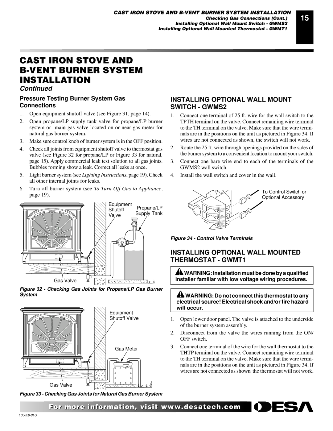
4.Check all joints from equipment shutoff valve to thermostat gas valve (see Figure 32 for propane/LP or Figure 33 for natural, page 15). Apply commercial leak test solution to all gas joints. Bubbles forming show a leak. Correct all leaks at once.

5.Light burner system (see Lighting Instructions, page 19). Check all other internal joints for leaks.

6.Turn off burner system (see To Turn Off Gas to Appliance, page 19).

Equipment

Propane/LP

Shutoff

Supply Tank

Valve


Gas Valve


Figure 32 - Checking Gas Joints for Propane/LP Gas Burner System

INSTALLING OPTIONAL WALL MOUNT SWITCH - GWMS2

1.Connect one terminal of 25 ft. wire for the wall switch to the TPTH terminal on the valve. Connect remaining wire terminal to the TH terminal on the valve. Make sure that the wire termi- nals are in the positions on the unit as pictured in Figure 34. If wires are not connected as shown, the switch will not work.

2.Route the 25 ft. wire through openings provided on the sides of the burner system to a convenient location to mount your switch.

3.Connect one bare wire end to each of the terminals of the GWMS2 wall switch.

4.Install the wall switch and cover in the wall.

To Control Switch or

Optional Accessory

Figure 34 - Control Valve Terminals

INSTALLING OPTIONAL WALL MOUNTED THERMOSTAT - GWMT1

WARNING: Installation must be done by a qualified installer familiar with low voltage wiring procedures.

WARNING: Do not connect this thermostat to any electrical source! Electrical shock and/or fire hazard

Gas Valve

Equipment Shutoff Valve

Gas Meter

will occur.

1.Open lower door panel. The valve is attached to the underside of the burner system assembly.

2.Disconnect from the valve the wires running from the ON/ OFF switch.

3.Connect one terminal of the wire for the wall thermostat to the THTP terminal on the valve. Connect remaining wire terminal to the TH terminal on the valve. Make sure that the wire termi- nals are in the positions on the unit as pictured in Figure 34. If wires are not connected as shown the thermostat will not work.

Figure 33 - Checking Gas Joints for Natural Gas Burner System

For morevisit www..com

106828-01C

Page 15
Image 15
Desa SBVBP(C), SBVBN(C) Installing Optional Wall Mount Switch GWMS2, Installing Optional Wall Mounted Thermostat GWMT1

SBVBP(C), SBVBN(C) specifications

Desa SBVBP(C) and SBVBN(C) are two advanced models in the landscape of environmental and energy-efficient technologies. These innovative designs are at the forefront of sustainable construction, showcasing a plethora of features and characteristics that make them stand out.

One of the main features of Desa SBVBP(C) is its emphasis on bioclimatic architecture, which ensures that buildings harmonize with their surrounding environment. This model incorporates passive solar design principles, allowing natural light to penetrate efficiently while minimizing energy loss. High-performance thermal insulation is another significant characteristic, which helps maintain comfortable indoor temperatures regardless of external weather conditions.

Desa SBVBN(C) complements its counterpart with its remarkable integration of renewable energy technologies. Equipped with photovoltaic panels and wind turbine systems, this model harnesses natural energy sources to reduce reliance on non-renewable energy. The energy generated can be used for lighting, heating, and powering appliances, making the building self-sufficient and cost-effective over time.

Both models utilize smart technology for enhanced operational efficiency. Internet of Things (IoT) devices allow for real-time monitoring and control of energy consumption, promoting sustainable living practices among residents. Automated systems adjust lighting, heating, and cooling based on occupancy and time of day, further contributing to energy savings.

Water conservation is another crucial aspect of Desa SBVBP(C) and SBVBN(C). Both designs implement rainwater harvesting systems and greywater recycling technologies, ensuring that water usage is minimized and reused effectively. This not only lowers utility bills for occupants but also contributes to environmental sustainability by reducing the strain on local water resources.

The construction materials used in both models emphasize sustainability, utilizing recycled, locally sourced, and eco-friendly materials whenever possible. This commitment to green building practices ensures that the overall environmental footprint of the structures is minimal.

In summary, Desa SBVBP(C) and SBVBN(C) represent a paradigm shift towards eco-conscious living. Through the integration of advanced technologies, renewable energy sources, and smart systems, these models provide a blueprint for sustainable development that addresses the pressing challenges of climate change and environmental degradation. As cities around the world seek innovative solutions to improve urban living, models like these shine as beacons of hope and progress.