FIREPLACE INSTALLATION

20

Checking Gas Connections (Cont.)


Installing Optional Wall Mount Switch - GWMS2


FIREPLACE INSTALLATION

Continued

5.Reconnect fireplace and equipment shutoff valve to gas supply. Check reconnected fittings for leaks.

Test Pressures Equal To or Less Than 1/2 PSIG (3.5 kPa)

1.Close equipment shutoff valve (see Figure 33).

2.Pressurize supply piping system by either opening propane/LP supply tank valve for propane/LP gas fireplace or opening main gas valve located on or near gas meter for natural gas fireplace or using compressed air.

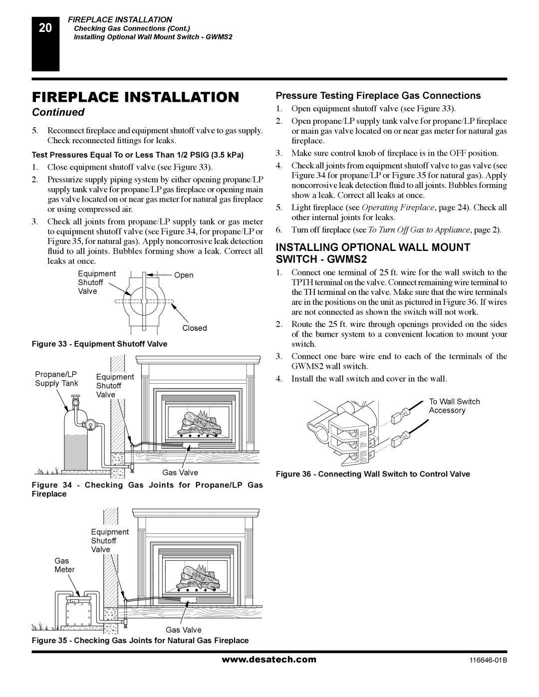
3.Check all joints from propane/LP supply tank or gas meter to equipment shutoff valve (see Figure 34, for propane/LP or Figure 35, for natural gas). Apply noncorrosive leak detection fluid to all joints. Bubbles forming show a leak. Correct all

leaks at once.

Equipment

Open

Shutoff


Valve


Closed

Figure 33 - Equipment Shutoff Valve

Pressure Testing Fireplace Gas Connections

1.Open equipment shutoff valve (see Figure 33).

2.Open propane/LP supply tank valve for propane/LP fireplace or main gas valve located on or near gas meter for natural gas fireplace.

3.Make sure control knob of fireplace is in the OFF position.

4.Check all joints from equipment shutoff valve to gas valve (see Figure 34 for propane/LP or Figure 35 for natural gas). Apply noncorrosive leak detection fluid to all joints. Bubbles forming show a leak. Correct all leaks at once.

5.Light fireplace (see Operating Fireplace, page 24). Check all other internal joints for leaks.

6.Turn off fireplace (see To Turn Off Gas to Appliance, page 2).

INSTALLING OPTIONAL WALL MOUNT SWITCH - GWMS2

1.Connect one terminal of 25 ft. wire for the wall switch to the TPTH terminal on the valve. Connect remaining wire terminal to the TH terminal on the valve. Make sure that the wire terminals are in the positions on the unit as pictured in Figure 36. If wires are not connected as shown the switch will not work.

2.Route the 25 ft. wire through openings provided on the sides of the burner system to a convenient location to mount your switch.


3.

Connect one bare wire end to each of the terminals of the

Propane/LP

Equipment


GWMS2 wall switch.

4.

Install the wall switch and cover in the wall.

Supply Tank

Shutoff


Valve


To Wall Switch


Accessory


Gas Valve

Figure 36 - Connecting Wall Switch to Control Valve

Figure 34 - Checking Gas Joints for Propane/LP Gas


Fireplace


Equipment


Shutoff


Valve


Gas


Meter


Gas Valve


Figure 35 - Checking Gas Joints for Natural Gas Fireplace


www.desatech.com

116646-01B

Page 20
Image 20
Desa T32N-A, CGDV32NR, T32P-A, CGDV32PR, (V)T32P-A SERIES, (V)T32N-A SERIES Installing Optional Wall Mount Switch GWMS2

(V)T32P-A SERIES, (V)T32N-A SERIES, T32N-A, CGDV32NR, T32P-A, CGDV32PR specifications

The T32N-A, CGDV32NR, T32P-A, CGDV32PR, (V)T32P-A SERIES, and (V)T32N-A SERIES are distinguished series of innovative technologies designed to meet diverse industrial demands. These models exemplify cutting-edge engineering, tailored for performance, efficiency, and adaptability.

One of the primary features of these series is their robust construction. The T32N-A and its counterparts are built with high-quality materials, ensuring durability and longevity even in harsh operating conditions. This reliability makes them ideal for applications that require consistent performance under stress. The engineering design incorporates advanced computational techniques, resulting in streamlined shapes that enhance aerodynamic efficiency.

The CGDV32NR and CGDV32PR series are particularly notable for their fluid management capabilities. These models are equipped with sophisticated flow control technologies that optimize the movement of fluids, minimizing waste and energy consumption. This efficiency is crucial for industries such as water treatment, chemical processing, and food production, where resource conservation is paramount.

Additionally, the (V)T32P-A and (V)T32N-A SERIES introduce variable technology options, allowing for enhanced versatility in operation. These models feature adjustable parameters that can be fine-tuned to suit specific processes, making them adaptable for various industrial applications. This flexibility minimizes downtime and maximizes productivity, providing a significant competitive edge.

In terms of user interface, these series emphasize user-friendly controls and robust monitoring systems. Operators can easily track performance metrics and make real-time adjustments, ensuring optimal functionality. Advanced sensors integrated into the systems enhance safety by providing alerts and diagnostics that preempt potential issues.

Environmental considerations are also a critical focus of these series. The T32N-A and associated models are designed with energy efficiency in mind, aligning with contemporary sustainability goals across industries. Reduced energy consumption and lower emissions are significant advantages, contributing to a smaller ecological footprint.

Overall, the T32N-A, CGDV32NR, T32P-A, CGDV32PR, (V)T32P-A SERIES, and (V)T32N-A SERIES stand out for their exceptional features, intuitive technology, and adaptability. Suitable for various industrial applications, they represent the forefront of innovation, combining performance and efficiency to meet the evolving demands of modern industry. As businesses continue to prioritize reliability and sustainability, these series are poised to play a critical role in driving progress across sectors.