6

LOCATION OF TERMINATION CAP

LOCATION OF TERMINATION CAP

D

E V

B L


C


Fixed


V


Closed


F


V


Openable


B

B

B

Openable Fixed Closed

H

V

B

I

V J XG

AM

NN


G


V


G

V K X

V


A

V TERMINATION CAP

X AIR SUPPLY INLET

G GAS METER

RESTRICTED AREA (TERMINATION PROHIBITED)

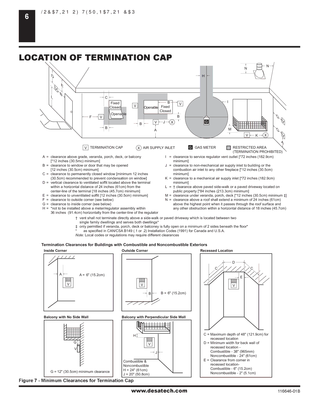
A= clearance above grade, veranda, porch, deck, or balcony [*12 inches (30.5mc) minimum]

B= clearance to window or door that may be opened [12 inches (30.5cm) minimum]

C = clearance to permanently closed window [minimum 12 inches (30.5cm) recommended to prevent condensation on window]

D = vertical clearance to ventilated soffit located above the terminal within a horizontal distance of 24 inches (61cm) from the center-line of the terminal [18 inches (45.7cm) minimum]

E= clearance to unventilated soffit [12 inches (30.5cm) minimum] F = clearance to outside corner (see below)

G = clearance to inside corner (see below)

H = *not to be installed above a meter/regulator assembly within

36 inches (91.4cm) horizontally from the center-line of the regulator

I= clearance to service regulator vent outlet [*72 inches (182.9cm) minimum]

J= clearance to non-mechanical air supply inlet to building or the combustion air inlet to any other fireplace [*12 inches (30.5cm)

minimum]

K= clearance to a mechanical air supply inlet [*72 inches (182.9cm) minimum]

L= † clearance above paved side-walk or a paved driveway located on public property [*84 inches (213.3cm) minimum]

M = clearance under veranda, porch, deck [*12 inches (30.5cm) minimum ‡]

N= clearance above a roof shall extend a minimum of 24 inches (61cm) above the highest point when it passes through the roof surface and any other obstruction within a horizontal distance of 18 inches (45.7cm)

† vent shall not terminate directly above a side-walk or paved driveway which is located between two single family dwellings and serves both dwellings*

only permitted if veranda, porch, deck or balconey is fully open on a minimum of 2 sides beneath the floor* * as specified in CAN/CSA B149 (.1 or .2) Installation Codes (1991) for Canada and U.S.A.

Note: Local codes or regulations may require different clearances

Termination Clearances for Buildings with Combustible and Noncombustible Exteriors

Inside Corner

Outside Corner

Recessed Location

AA = 6" (15.2cm)

V

Balcony with No Side Wall

G

V

G = 12" (30.5cm) minimum clearance

V

B B = 6" (15.2cm)

Balcony with Perpendicular Side Wall

H

V

J

Combustible &

Noncombustible

H = 24" (61cm)

J = 20" (50.8cm)


D

C

C

E

V

C = Maximum depth of 48" (121.9cm) for recessed location

D = Minimum width for back wall of recessed location - Combustible - 38" (965mm) Noncombustible - 24" (61cm)

E = Clearance from corner in recessed location- Combustible - 6" (15.2cm) Noncombustible - 2" (5.1cm)

Figure 7 - Minimum Clearances for Termination Cap

www.desatech.com

116646-01B

Page 6
Image 6
Desa T32N-A, CGDV32NR, T32P-A, CGDV32PR Location of Termination CAP, Termination CAP AIR Supply Inlet GAS Meter

(V)T32P-A SERIES, (V)T32N-A SERIES, T32N-A, CGDV32NR, T32P-A, CGDV32PR specifications

The T32N-A, CGDV32NR, T32P-A, CGDV32PR, (V)T32P-A SERIES, and (V)T32N-A SERIES are distinguished series of innovative technologies designed to meet diverse industrial demands. These models exemplify cutting-edge engineering, tailored for performance, efficiency, and adaptability.

One of the primary features of these series is their robust construction. The T32N-A and its counterparts are built with high-quality materials, ensuring durability and longevity even in harsh operating conditions. This reliability makes them ideal for applications that require consistent performance under stress. The engineering design incorporates advanced computational techniques, resulting in streamlined shapes that enhance aerodynamic efficiency.

The CGDV32NR and CGDV32PR series are particularly notable for their fluid management capabilities. These models are equipped with sophisticated flow control technologies that optimize the movement of fluids, minimizing waste and energy consumption. This efficiency is crucial for industries such as water treatment, chemical processing, and food production, where resource conservation is paramount.

Additionally, the (V)T32P-A and (V)T32N-A SERIES introduce variable technology options, allowing for enhanced versatility in operation. These models feature adjustable parameters that can be fine-tuned to suit specific processes, making them adaptable for various industrial applications. This flexibility minimizes downtime and maximizes productivity, providing a significant competitive edge.

In terms of user interface, these series emphasize user-friendly controls and robust monitoring systems. Operators can easily track performance metrics and make real-time adjustments, ensuring optimal functionality. Advanced sensors integrated into the systems enhance safety by providing alerts and diagnostics that preempt potential issues.

Environmental considerations are also a critical focus of these series. The T32N-A and associated models are designed with energy efficiency in mind, aligning with contemporary sustainability goals across industries. Reduced energy consumption and lower emissions are significant advantages, contributing to a smaller ecological footprint.

Overall, the T32N-A, CGDV32NR, T32P-A, CGDV32PR, (V)T32P-A SERIES, and (V)T32N-A SERIES stand out for their exceptional features, intuitive technology, and adaptability. Suitable for various industrial applications, they represent the forefront of innovation, combining performance and efficiency to meet the evolving demands of modern industry. As businesses continue to prioritize reliability and sustainability, these series are poised to play a critical role in driving progress across sectors.