FIREPLACE INSTALLATION

Installing Optional Blower Accessories (Cont.)

17

FIREPLACE INSTALLATION

Continued

4.Be certain that all wire terminals are securely attached to ter- minals on blower motor and that the screw retaining the green ground wire is tight.

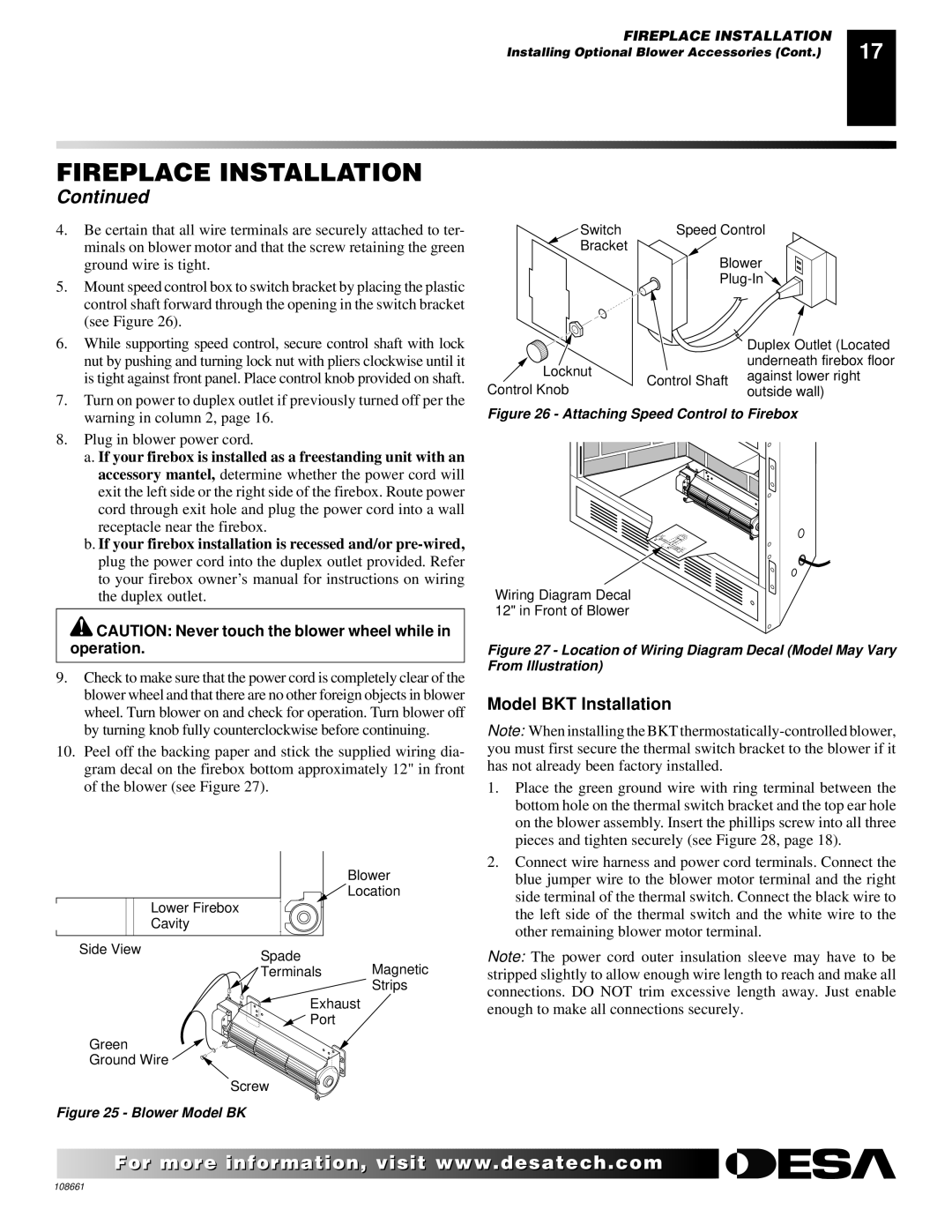
5.Mount speed control box to switch bracket by placing the plastic control shaft forward through the opening in the switch bracket (see Figure 26).

6.While supporting speed control, secure control shaft with lock nut by pushing and turning lock nut with pliers clockwise until it is tight against front panel. Place control knob provided on shaft.

7.Turn on power to duplex outlet if previously turned off per the warning in column 2, page 16.

8.Plug in blower power cord.

a.If your firebox is installed as a freestanding unit with an accessory mantel, determine whether the power cord will exit the left side or the right side of the firebox. Route power cord through exit hole and plug the power cord into a wall receptacle near the firebox.

b.If your firebox installation is recessed and/or pre-wired, plug the power cord into the duplex outlet provided. Refer to your firebox owner’s manual for instructions on wiring the duplex outlet.

CAUTION: Never touch the blower wheel while in operation.

9.Check to make sure that the power cord is completely clear of the blower wheel and that there are no other foreign objects in blower wheel. Turn blower on and check for operation. Turn blower off by turning knob fully counterclockwise before continuing.

10.Peel off the backing paper and stick the supplied wiring dia- gram decal on the firebox bottom approximately 12" in front of the blower (see Figure 27).


Blower


Location


Lower Firebox


Cavity


Side View

Spade


Magnetic


Terminals


Strips

Exhaust

Port

Green

Ground Wire

Screw

Figure 25 - Blower Model BK

Switch

Speed Control

Bracket


Blower


Plug-In


Duplex Outlet (Located

Locknut


underneath firebox floor

Control Shaft

against lower right

Control Knob

outside wall)


Figure 26 - Attaching Speed Control to Firebox

Wiring Diagram Decal

12" in Front of Blower

Figure 27 - Location of Wiring Diagram Decal (Model May Vary From Illustration)

Model BKT Installation

Note: When installing the BKT thermostatically-controlled blower, you must first secure the thermal switch bracket to the blower if it has not already been factory installed.

1.Place the green ground wire with ring terminal between the bottom hole on the thermal switch bracket and the top ear hole on the blower assembly. Insert the phillips screw into all three pieces and tighten securely (see Figure 28, page 18).

2.Connect wire harness and power cord terminals. Connect the blue jumper wire to the blower motor terminal and the right side terminal of the thermal switch. Connect the black wire to the left side of the thermal switch and the white wire to the other remaining blower motor terminal.

Note: The power cord outer insulation sleeve may have to be stripped slightly to allow enough wire length to reach and make all connections. DO NOT trim excessive length away. Just enable enough to make all connections securely.

For morevisit www..com

108661

Page 17
Image 17
Desa T32N, T36N, T32P, T36P installation manual Model BKT Installation, Blower Model BK

T32N, T36N, T32P, T36P specifications

Desa T32N, T36N, T32P, and T36P are prominent technologies that represent the cutting-edge advancements in the field of telecommunications and data transmission. These systems are crucial for a variety of applications, including telecommunications networks, data centers, and various other technological infrastructures that require high-speed and reliable data transfer capabilities.

Starting with the T32N and T36N models, these systems are characterized by their exceptional bandwidth capacity and high processing speeds. They are designed to cater to the growing demand for faster internet connections and efficient data handling. One of the main features of these models is their ability to support multiple channels simultaneously, allowing for numerous data streams to be processed at once. This is particularly beneficial for environments where data traffic is high, such as urban areas and corporate networks. The T32N and T36N utilize advanced modulation techniques to enhance signal quality, effectively minimizing interference and increasing overall throughput.

On the other hand, the T32P and T36P models are specially engineered for optimal performance under varying network conditions. These models are equipped with adaptive technologies that automatically adjust to network demands, ensuring consistent data delivery even during peak usage periods. The main trait of these systems is their resilience; they are built to withstand fluctuations in data traffic and environmental factors, making them suitable for deployment in diverse settings, from rural areas to densely populated cities.

All four models leverage state-of-the-art technologies such as MIMO (Multiple Input Multiple Output) and beamforming to maximize efficiency and coverage. MIMO technology allows these systems to transmit and receive multiple data streams simultaneously, significantly boosting the data rate and overall system capacity. Beamforming enhances the directivity of the signal, focusing the transmission toward specific receivers, which not only improves signal strength but also reduces interference with other devices.

Another noteworthy characteristic of the Desa T32N, T36N, T32P, and T36P family is their compatibility with a wide range of existing technologies and infrastructures. This interoperability allows for seamless integration into current systems, facilitating upgrades without the need for complete overhauls. As the landscape of technology continues to evolve, these models stand out for their robust features and adaptive capabilities, solidifying their position as essential tools in the advancement of telecommunications and data transfer solutions.