6

LOCATION OF TERMINATION CAP

LOCATION OF TERMINATION CAP

D

E V

B L


C


Fixed


V


Closed


F


V


Openable


B

B

B

Openable Fixed Closed

H

V

B

I

V J XG

AM

NN


G


V


G

V K X

V


A

V TERMINATION CAP

X AIR SUPPLY INLET

G GAS METER

RESTRICTED AREA (TERMINATION PROHIBITED)

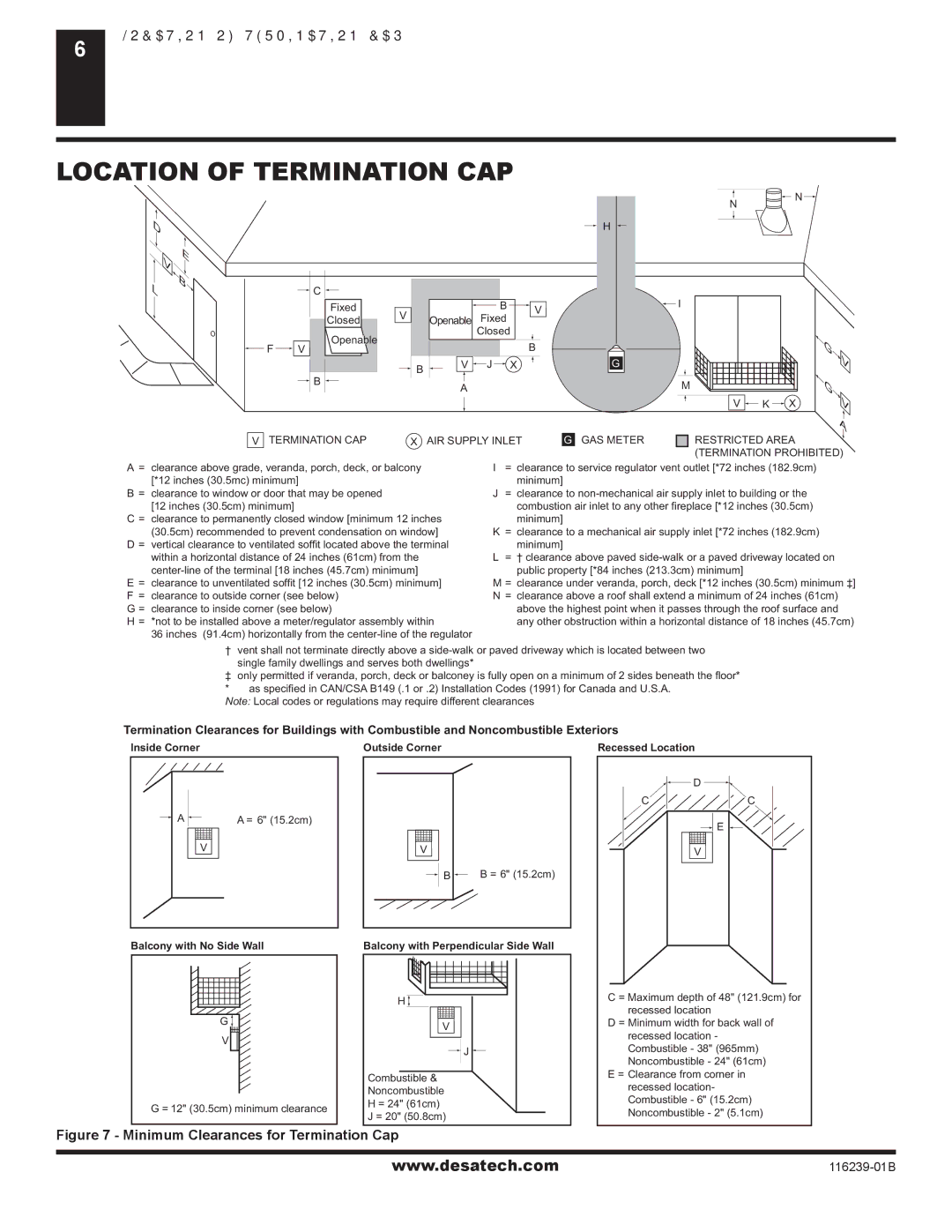
A= clearance above grade, veranda, porch, deck, or balcony [*12 inches (30.5mc) minimum]

B= clearance to window or door that may be opened [12 inches (30.5cm) minimum]

C = clearance to permanently closed window [minimum 12 inches (30.5cm) recommended to prevent condensation on window]

D = vertical clearance to ventilated soffit located above the terminal within a horizontal distance of 24 inches (61cm) from the center-line of the terminal [18 inches (45.7cm) minimum]

E= clearance to unventilated soffit [12 inches (30.5cm) minimum] F = clearance to outside corner (see below)

G = clearance to inside corner (see below)

H = *not to be installed above a meter/regulator assembly within

36 inches (91.4cm) horizontally from the center-line of the regulator

I= clearance to service regulator vent outlet [*72 inches (182.9cm) minimum]

J= clearance to non-mechanical air supply inlet to building or the combustion air inlet to any other fireplace [*12 inches (30.5cm)

minimum]

K= clearance to a mechanical air supply inlet [*72 inches (182.9cm) minimum]

L= † clearance above paved side-walk or a paved driveway located on public property [*84 inches (213.3cm) minimum]

M = clearance under veranda, porch, deck [*12 inches (30.5cm) minimum ‡]

N= clearance above a roof shall extend a minimum of 24 inches (61cm) above the highest point when it passes through the roof surface and any other obstruction within a horizontal distance of 18 inches (45.7cm)

† vent shall not terminate directly above a side-walk or paved driveway which is located between two single family dwellings and serves both dwellings*

only permitted if veranda, porch, deck or balconey is fully open on a minimum of 2 sides beneath the floor* * as specified in CAN/CSA B149 (.1 or .2) Installation Codes (1991) for Canada and U.S.A.

Note: Local codes or regulations may require different clearances

Termination Clearances for Buildings with Combustible and Noncombustible Exteriors

Inside Corner

Outside Corner

Recessed Location

AA = 6" (15.2cm)

V

Balcony with No Side Wall

G

V

G = 12" (30.5cm) minimum clearance

V

B B = 6" (15.2cm)

Balcony with Perpendicular Side Wall

H

V

J

Combustible &

Noncombustible

H = 24" (61cm)

J = 20" (50.8cm)


D

C

C

E

V

C = Maximum depth of 48" (121.9cm) for recessed location

D = Minimum width for back wall of recessed location - Combustible - 38" (965mm) Noncombustible - 24" (61cm)

E = Clearance from corner in recessed location- Combustible - 6" (15.2cm) Noncombustible - 2" (5.1cm)

Figure 7 - Minimum Clearances for Termination Cap

www.desatech.com

116239-01B

Page 6
Image 6
Desa (V)KC42P SERIES, (V)KC42N Series Location of Termination CAP, Termination CAP AIR Supply Inlet GAS Meter

(V)KC42N Series, (V)KC42P SERIES specifications

The Desa (V)KC42P SERIES and (V)KC42N Series represent a significant advancement in the field of heating solutions, designed to enhance comfort while optimizing energy efficiency. These innovative heating systems are engineered for residential and commercial applications, making them versatile for various environments.

One of the standout features of the Desa (V)KC42P and (V)KC42N Series is their advanced control technologies. Equipped with smart thermostatic controls, these units allow users to manage their heating needs with precision. The intuitive user interface provides an easy way to adjust settings, ensuring that the desired temperature is achieved while minimizing energy consumption.

The efficiency of the (V)KC42P and (V)KC42N Series is further enhanced by their state-of-the-art combustion technology. These models utilize a unique burner design that maximizes heat output while reducing emissions. This not only supports environmental sustainability but also ensures that users save on energy costs without compromising performance.

Safety is another paramount feature of these heating systems. The Desa series incorporates multiple fail-safes, including overheat protection and automatic shut-off mechanisms. These features are designed to provide peace of mind for users, knowing that their home or business is equipped with a system that prioritizes safety.

Durability and reliability are also hallmarks of the Desa (V)KC42P and (V)KC42N Series. Constructed with high-quality materials, these units are built to withstand the rigors of daily use while maintaining an aesthetically pleasing design. This ensures they complement any décor while delivering consistent performance across seasons.

In terms of installation, both series come with flexible options. They can be easily integrated into existing setups, making upgrades or replacements hassle-free. The user-friendly installation procedures reduce downtime, allowing users to enjoy the benefits of their new heating system almost immediately.

Additionally, the (V)KC42P and (V)KC42N Series are designed with versatility in mind. They can accommodate various heating methods, from forced air to radiant heating, making them suitable for different heating preferences and system requirements.

In summary, the Desa (V)KC42P and (V)KC42N Series are engineered to provide superior heating performance, energy efficiency, and safety. With advanced technology, durable construction, and user-friendly features, these heating solutions stand out in the market as reliable options for any heating need.