VENTING INSTALLATION INSTRUCTIONS

Installation for Vertical Termination

13

VENTING INSTALLATION INSTRUCTIONS

Continued

INSTALLATION FOR VERTICAL TERMINATION

Note: Vertical restrictor must be installed in all vertical installa- tions.

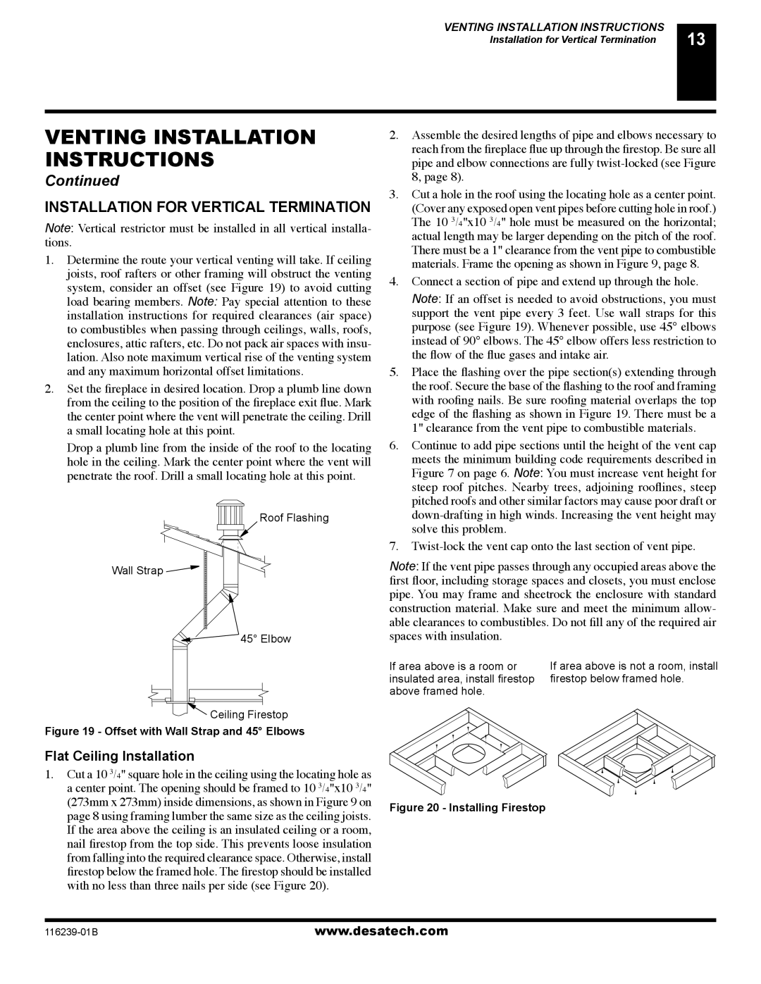
1.Determine the route your vertical venting will take. If ceiling joists, roof rafters or other framing will obstruct the venting system, consider an offset (see Figure 19) to avoid cutting load bearing members. Note: Pay special attention to these installation instructions for required clearances (air space) to combustibles when passing through ceilings, walls, roofs, enclosures, attic rafters, etc. Do not pack air spaces with insu- lation. Also note maximum vertical rise of the venting system and any maximum horizontal offset limitations.

2.Set the fireplace in desired location. Drop a plumb line down from the ceiling to the position of the fireplace exit flue. Mark the center point where the vent will penetrate the ceiling. Drill a small locating hole at this point.

Drop a plumb line from the inside of the roof to the locating hole in the ceiling. Mark the center point where the vent will penetrate the roof. Drill a small locating hole at this point.

Roof Flashing

Wall Strap

45° Elbow

Ceiling Firestop

Figure 19 - Offset with Wall Strap and 45° Elbows

Flat Ceiling Installation

1.Cut a 10 3/4" square hole in the ceiling using the locating hole as a center point. The opening should be framed to 10 3/4"x10 3/4" (273mm x 273mm) inside dimensions, as shown in Figure 9 on page 8 using framing lumber the same size as the ceiling joists. If the area above the ceiling is an insulated ceiling or a room, nail firestop from the top side. This prevents loose insulation from falling into the required clearance space. Otherwise, install firestop below the framed hole. The firestop should be installed with no less than three nails per side (see Figure 20).

2.Assemble the desired lengths of pipe and elbows necessary to reach from the fireplace flue up through the firestop. Be sure all pipe and elbow connections are fully twist-locked (see Figure 8, page 8).

3.Cut a hole in the roof using the locating hole as a center point. (Cover any exposed open vent pipes before cutting hole in roof.) The 10 3/4"x10 3/4" hole must be measured on the horizontal; actual length may be larger depending on the pitch of the roof. There must be a 1" clearance from the vent pipe to combustible materials. Frame the opening as shown in Figure 9, page 8.

4.Connect a section of pipe and extend up through the hole.

Note: If an offset is needed to avoid obstructions, you must support the vent pipe every 3 feet. Use wall straps for this purpose (see Figure 19). Whenever possible, use 45° elbows instead of 90° elbows. The 45° elbow offers less restriction to the flow of the flue gases and intake air.

5.Place the flashing over the pipe section(s) extending through the roof. Secure the base of the flashing to the roof and framing with roofing nails. Be sure roofing material overlaps the top edge of the flashing as shown in Figure 19. There must be a 1" clearance from the vent pipe to combustible materials.

6.Continue to add pipe sections until the height of the vent cap meets the minimum building code requirements described in Figure 7 on page 6. Note: You must increase vent height for steep roof pitches. Nearby trees, adjoining rooflines, steep pitched roofs and other similar factors may cause poor draft or down-drafting in high winds. Increasing the vent height may solve this problem.

7.Twist-lock the vent cap onto the last section of vent pipe.

Note: If the vent pipe passes through any occupied areas above the first floor, including storage spaces and closets, you must enclose pipe. You may frame and sheetrock the enclosure with standard construction material. Make sure and meet the minimum allow- able clearances to combustibles. Do not fill any of the required air spaces with insulation.

If area above is a room or

If area above is not a room, install

insulated area, install firestop

firestop below framed hole.

above framed hole.


Figure 20 - Installing Firestop

116239-01B

www.desatech.com

Page 13
Image 13
Desa (V)KC42N Series, (V)KC42P SERIES installation manual Installation for Vertical Termination, Flat Ceiling Installation

(V)KC42N Series, (V)KC42P SERIES specifications

The Desa (V)KC42P SERIES and (V)KC42N Series represent a significant advancement in the field of heating solutions, designed to enhance comfort while optimizing energy efficiency. These innovative heating systems are engineered for residential and commercial applications, making them versatile for various environments.

One of the standout features of the Desa (V)KC42P and (V)KC42N Series is their advanced control technologies. Equipped with smart thermostatic controls, these units allow users to manage their heating needs with precision. The intuitive user interface provides an easy way to adjust settings, ensuring that the desired temperature is achieved while minimizing energy consumption.

The efficiency of the (V)KC42P and (V)KC42N Series is further enhanced by their state-of-the-art combustion technology. These models utilize a unique burner design that maximizes heat output while reducing emissions. This not only supports environmental sustainability but also ensures that users save on energy costs without compromising performance.

Safety is another paramount feature of these heating systems. The Desa series incorporates multiple fail-safes, including overheat protection and automatic shut-off mechanisms. These features are designed to provide peace of mind for users, knowing that their home or business is equipped with a system that prioritizes safety.

Durability and reliability are also hallmarks of the Desa (V)KC42P and (V)KC42N Series. Constructed with high-quality materials, these units are built to withstand the rigors of daily use while maintaining an aesthetically pleasing design. This ensures they complement any décor while delivering consistent performance across seasons.

In terms of installation, both series come with flexible options. They can be easily integrated into existing setups, making upgrades or replacements hassle-free. The user-friendly installation procedures reduce downtime, allowing users to enjoy the benefits of their new heating system almost immediately.

Additionally, the (V)KC42P and (V)KC42N Series are designed with versatility in mind. They can accommodate various heating methods, from forced air to radiant heating, making them suitable for different heating preferences and system requirements.

In summary, the Desa (V)KC42P and (V)KC42N Series are engineered to provide superior heating performance, energy efficiency, and safety. With advanced technology, durable construction, and user-friendly features, these heating solutions stand out in the market as reliable options for any heating need.