WHAT TO DO IF YOU SMELL GAS
Table of Contents
Safety Information
SAFETY INFORMATION
Continued
Continued
SAFETY INFORMATION
Local Codes
Safety Device
OPTIONAL REMOTE CONTROL accessory
Operation
Piezo Ignition System
Product Specifications
Figure 3 - Firebox Dimensions
Locating Firebox
Planning
Air For Combustion and Ventilation
PROVIDING ADEQUATE VENTILATION
DETERMINING FRESH-AIRFLOW FOR HEATER LOCATION
AIR FOR COMBUSTION AND VENTILATION
Continued
Installation
AIR FOR COMBUSTION AND VENTILATION
INSTALLATION CLEARANCES
Built-InFirebox Installation
raise the mantel to an accept- able height
remove the mantel
Continued
Rough Opening Dimensions for Built-inInstallation
Figure 8 - Rough Opening for Installing in Wall
Figure 9 - Rough Opening for Installing
in Corner Wall
Installing Firebox USING
OPTIONAL ACCESSORY MANTELS
Installing Gas Piping to Fireplace Location
Hearth
Accessories, page
Continued
Figure 14 - External Regulator With Vent
Pointing Down
CONNECTING Fireplace to Gas Supply
Assembly From Fireplace
Figure 16 - Removing Log Base
Figure 17 - Attaching Flexible Gas Lines Together
CHECKING GAS CONNECTIONS
Continued
Figure 18 - Equipment Shutoff Valve
Figure 19 - Checking Gas Joints for Natural Gas
Figure 22 - Installing Top Logs
INSTALLING LOGS
Figure 21 - Installing Bottom Logs
Hard-wiringFirebox
INSTALLING FIREPLACE HOOD AND SCREEN
Figure 23 - Hard-WiringFirebox
Figure 24 - Hood Placement
Thermostat Models FOR YOUR SAFETY
READ BEFORE LIGHTING
LIGHTING INSTRUCTIONS
Figure 26 - Control Knob and Ignitor
MANUAL LIGHTING PROCEDURE
Remote Control Models FOR YOUR SAFETY
Continued
THERMOSTAT CONTROL OPERATION
LIGHTING INSTRUCTIONS
MANUAL LIGHTING PROCEDURE
OPERATING FIREPLACE
BLOWER
Continued
Continued
On/Off Series Model HRC100
Thermostat Series Model hrc200
Figure 32 - On/Off Hand-HeldRemote
see Troubleshooting, page
Continued
PILOT FLAME PATTERN
Cleaning and Maintenance
Burner Injector Holder and Pilot Air Inlet Hole
Wiring Diagram
Replacement Parts
Specifications
Technical Service
Troubleshooting
OBSERVED PROBLEM
POSSIBLE CAUSE
REMEDY
OBSERVED PROBLEM
and Maintenance, page
Diagram, page
and Maintenance, page
OBSERVED PROBLEM
see Cleaning and Mainte
and Maintenance, page
Maintenance, page
OBSERVED PROBLEM
and Maintenance, page
Continued
POSSIBLE CAUSE
CLEANING KIT - GCK/CCK
RECEIVER AND HAND-HELDREMOTE CONTROL KIT - HRC100
WALL-MOUNTTHERMOSTAT SWITCH - GWMT1 Not Shown
WALL-MOUNTON/OFF SWITCH GWMS2 Not Shown
119305-01A
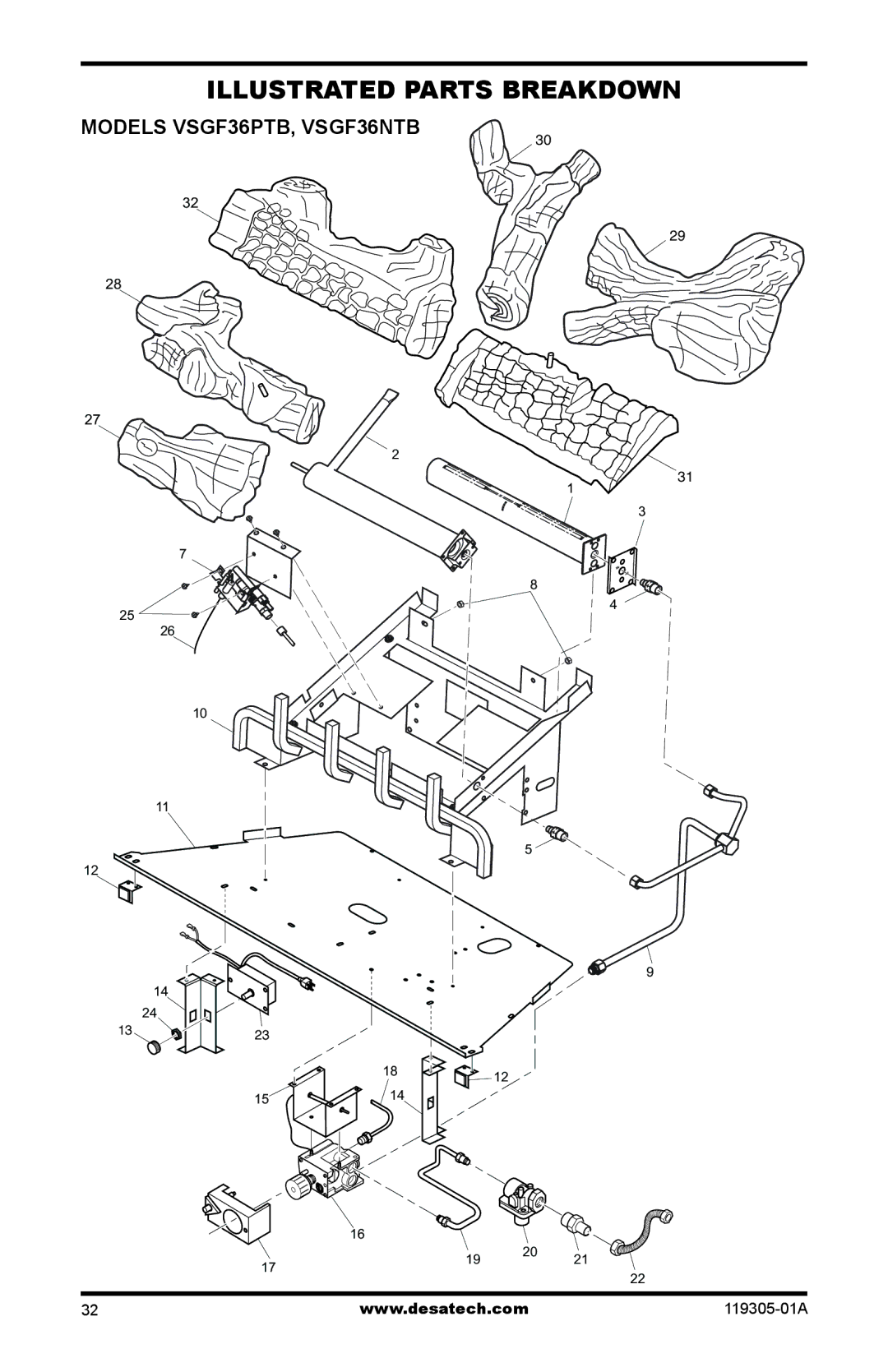
Illustrated Parts Breakdown
Models VSGF36PTB, VSGF36NTB
Parts List
119305-01A
ILLUSTRATED PARTS BREAKDOWN
Models VSGF36PRB, VSGF36NRB
PARTS LIST
119305-01A
1 113190-01CK Screen
119305-01A
119305-01A
LIMITED WARRANTY VENT-FREEGAS FIREPLACE SYSTEM
Warranty Information
KEEP THIS WARRANTY