Installation
Continued
1.Frame in rough opening. The firebox framing should be constructed of 2 x 4 lumber or heavier. Use dimensions in Table 1 and rough opening layout in Figure 8. Adjust framing so that firebox flushes with finished wall surface. If installing in a corner, use dimensions in Figures 8 and 9 for rough opening.
2.Install gas piping to firebox location. See Installing Gas Piping to Fireplace Location on page 13 and Connecting Fireplace to Gas Supply, page 15.
IMPORTANT: If installing blower accessory (circulating models with louvers only), see Hard- Wiring Firebox, page 18.
3.Carefully set firebox in front of rough open- ing with back of firebox inside wall opening. IMPORTANT: If installing a perimeter trim kit, see instructions included with trim acces- sory. You must install shoulder screws from trim kit now.
4.Carefully insert firebox into rough opening.
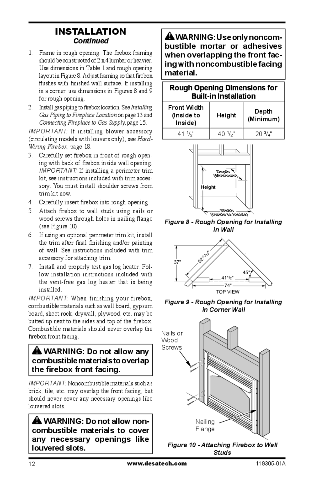
5.Attach firebox to wall studs using nails or wood screws through holes in nailing flange (see Figure 10).
6.If using an optional perimeter trim kit, install the trim after final finishing and/or painting of wall. See instructions included with trim accessory for attaching trim.
7.Install and properly test gas log heater. Fol- low installation instructions included with the
IMPORTANT: When finishing your firebox, combustible materials such as wall board, gypsum board, sheet rock, drywall, plywood, etc. may be butted up next to the sides and top of the firebox. Combustible materials should never overlap the firebox front facing.
![]() WARNING: Do not allow any combustiblematerialstooverlap the firebox front facing.
WARNING: Do not allow any combustiblematerialstooverlap the firebox front facing.
IMPORTANT: Noncombustible materials such as brick, tile, etc. may overlap the front facing, but should never cover any necessary openings like louvered slots.
![]() WARNING: Do not allow non- combustible materials to cover any necessary openings like louvered slots.
WARNING: Do not allow non- combustible materials to cover any necessary openings like louvered slots.
![]() WARNING: Use only noncom- bustible mortar or adhesives when overlapping the front fac- ing with noncombustible facing material.
WARNING: Use only noncom- bustible mortar or adhesives when overlapping the front fac- ing with noncombustible facing material.
Rough Opening Dimensions for
Built-in Installation
Front Width |
| Depth | |
(Inside to | Height | ||
(Minimum) | |||
Inside) |
| ||
|
| ||
|
|
| |
41 1/2" | 40 1/2" | 20 3/4" |
Depth![]()
![]() (Minimum)
(Minimum)
Height
Width ![]() (InsidetoInside)
(InsidetoInside)
Figure 8 - Rough Opening for Installing
in Wall
|
|
| " |
|
|
| 2 |
|
|
| /3 |
|
|
| 11 |
37" | 2 | ||
5 |
| ||
45°![]() 411/2"
411/2" ![]()
![]()
74"
TOP VIEW
Figure 9 - Rough Opening for Installing
in Corner Wall
Nails or
Wood
Screws
Nailing
Flange
Figure 10 - Attaching Firebox to Wall
Studs
12 | www.desatech.com |