PreInstallation
Continued
Clearances
Minimum clearances to combustibles for the fireplace are as follows:
*Back and sides | 0" |
Perpendicular walls | 6" |
Floor | 0" |
Ceiling to louver opening | 42" |
Front | 36" |
Top of Standoffs | 0" |
Vent | (See venting instructions |
| for specific venting |
| clearances.) |
Combustible material with a maximum thick- ness of 5/8" may be flush with the top front of fireplace.
43 1/4"
33"
56 3/4"
28"
*For back and sides of fireplace, do not pack with insulation or other materials. 0" clear- ance to combustible materials are for framing purpose only.
NOTICE: This fireplace is intend- ed for use as supplemental heat. Use this fireplace along with your primary heating system. Do not install this fireplace as your primary heat source. If you have a central heating system, you may run system’s circulat- ing blower while using fireplace. This will help circulate the heat throughout the house.
framing and finishing
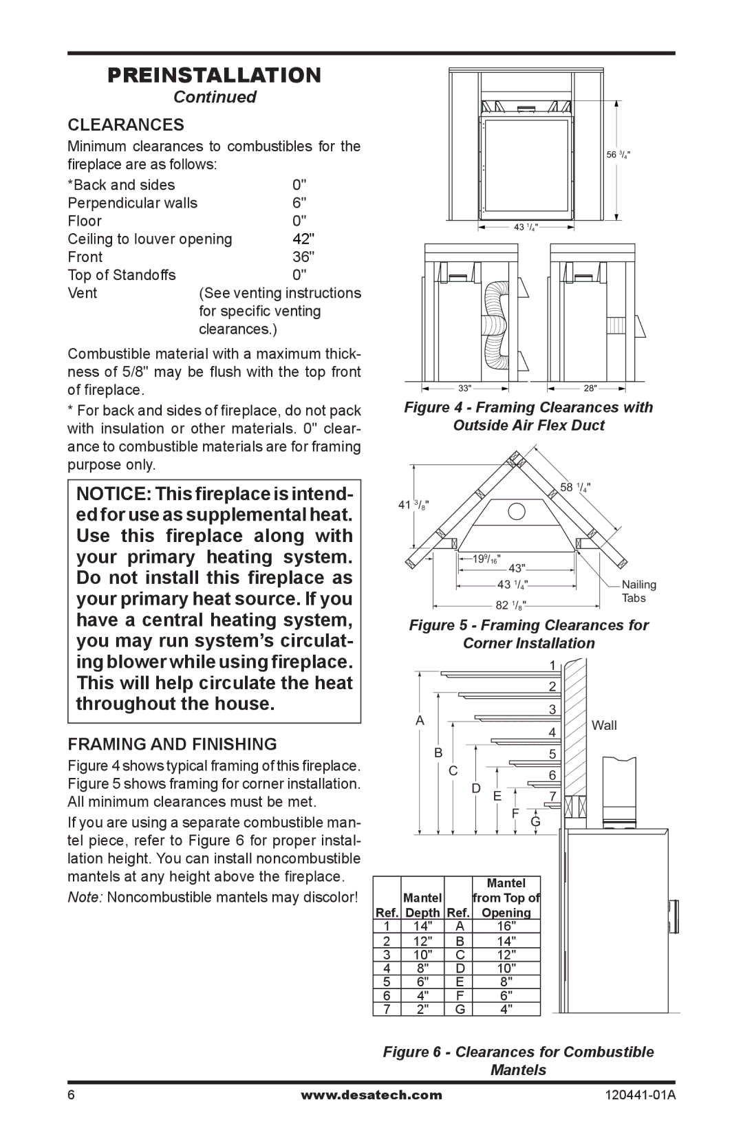
Figure 4 shows typical framing of this fireplace. Figure 5 shows framing for corner installation. All minimum clearances must be met.
If you are using a separate combustible man- tel piece, refer to Figure 6 for proper instal- lation height. You can install noncombustible mantels at any height above the fireplace.
Note: Noncombustible mantels may discolor!
Figure 4 - Framing Clearances with
Outside Air Flex Duct
|
|
|
|
| 58 1/4" |
| 41 3/8" |
|
|
|
|
|
|
| 199/16" |
|
|
|
|
| 43" |
|
|
|
|
| 43 1/4" |
| Nailing |
|
|
| 82 1/8" |
| Tabs |
|
|
|
|
| |
| Figure 5 - Framing Clearances for | ||||
|
| Corner Installation | |||
|
|
|
| 1 |
|
|
|
|
| 2 |
|
| A |
|
| 3 |
|
|
|
| 4 | Wall | |
|
|
|
| ||
|
|
|
|
| |
| B |
|
| 5 |
|
|
| C |
| 6 |
|
|
|
| D E |
| |
|
|
| 7 |
| |
|
|
| F | G |
|
|
|
| Mantel |
|
|
| Mantel |
| from Top of |
| |
Ref. Depth Ref. | Opening |
| |||
1 | 14" | A | 16" |
|
|
2 | 12" | B | 14" |
|
|
3 | 10" | C | 12" |
|
|
4 | 8" | D | 10" |
|
|
5 | 6" | E | 8" |
|
|
6 | 4" | F | 6" |
|
|
7 | 2" | G | 4" |
|
|
Figure 6 - Clearances for Combustible
Mantels
www.desatech.com120441-01A