FIG. 8
FIG. 10 | FIG. 12 |
English
SCREW
FIG.9
MITER
 LOCK/DETENT
ROD
measurement on the miter
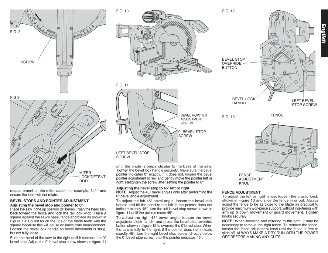
FIG. 11
BEVEL POINTER
ADJUSTMENT
SCREW
0˚ BEVEL STOP SCREW
LEFT BEVEL STOP
SCREW
until the blade is perpendicular to the base of the saw. Tighten the bevel lock handle securely. Make sure the bevel pointer indicates 0° exactly. If it does not, loosen the bevel pointer adjustment screw and gently move the pointer left or right. Retighten the screw after setting the pointer to 0°.
Adjusting the bevel stop to 45° left or right
BEVEL STOP
OVERRIDE
BUTTON
BEVEL LOCK
HANDLE
FIG. 13 | FENCE |
|
FENCE
ADJUSTMENT
KNOB
LEFT BEVEL STOP SCREW
ensure the table will not rotate.
BEVEL STOPS AND POINTER ADJUSTMENT Adjusting the bevel stop and pointer to 0°
Place the saw in the up position (0° bevel). Push the head fully back toward the fence and lock the rail lock knob. Place a square against the saw’s base, fence and blade as shown in Figure 10. Do not touch the tips of the blade teeth with the square because this will cause an inaccurate measurement. Loosen the bevel lock handle so bevel movement is snug, but not fully loose.
Push the head of the saw to the right until it contacts the 0° bevel stop. Adjust the 0˚ bevel stop screw shown in figure 11
NOTE: Adjust the 45° bevel angles only after performing the 0° bevel angle adjustment.
To adjust the left 45° bevel angle, loosen the bevel lock handle and tilt the head to the left. If the pointer does not indicate exactly 45°, turn the left bevel stop screw shown in figure 11 until the pointer reads 45°.
To adjust the right 45° bevel angle, loosen the bevel adjustment/lock handle and press the bevel stop override button shown in figure 12 to override the 0˚bevel stop. When the saw is fully to the right, if the pointer does not indicate exactly 45°, turn the right bevel stop screw (directly below the 0˚ bevel stop screw) until the pointer indicates 45°.
FENCE ADJUSTMENT
To adjust the left or right fence, loosen the plastic knob shown in Figure 13 and slide the fence in or out. Always adjust the fence to be as close to the blade as practical to provide maximum workpiece support, without interfering with arm up & down movement or guard movement. Tighten knobs securely.
NOTE: When beveling and mitering to the right, it may be necessary to remove the right fence. To remove the fence, loosen the fence adjustment knob until the fence is free to slide off. ALWAYS MAKE A DRY RUN WITH THE POWER OFF BEFORE MAKING ANY CUTS.
7