English
The inset box on page 14 gives the proper settings for cutting crown molding. (The angles for the miter and bevel settings are very precise and are not easy to accurately set on your saw.) Since most rooms do not have angles of precisely 90 degrees, you will have to fine tune your settings anyway.
NOTE: Pretesting with scrap materials is extremely important.
CUTTING CROWN MOLDING ANGLED BETWEEN THE FENCE AND TABLE (NESTED)
Use of the crown molding fence accessory (DW7084) is highly recommended because of its accuracy and conven- ience. The crown molding fence accessory is available for purchase from your local dealer.
The advantage to cutting crown molding using this method is that no bevel cut is required. Minute changes in the miter angle can be made without affecting the bevel angle. This way, when corners other than 90˚ are encountered, the saw can be quickly and easily adjusted for them. Use the crown molding fence accessory to maintain the angle at which the molding will be on the wall. To use the accessory, place the molding on the table at an angle between the fence and the saw table, as shown in figure 28.
Instructions for Cutting Crown Molding Angled between the Fence and Base of the Saw
1.Angle the molding so the bottom of the molding (part which goes against the wall when installed) is against the fence and the top of the molding is resting on the base of the saw, as shown in figure 28.
2.The angled “flats” on the back of the molding must rest squarely on the fence and base of the saw.
TO CUT AN INSIDE CORNER JOINT:
Cut the left side:
1. | set the miter at 45° right. |
2. | Save the right side of cut. |
FIG. 27
FENCE |
TABLE |
CROWN MOLDING FLAT ON TABLE AND AGAINST FENCE
FIG. 28 |
|
| BOTTOM OF |
| MOLDING |
| TOP OF |
BACK OF | MOLDING |
MOLDING | TABLE |
|
CROWN MOLDING BETWEEN FENCE AND TABLE
FIG. 29
ANGLE “A”
and locate that angle on the appropriate arc in the chart. From that point, follow the vertical line that intersects the arc at that
Special Cuts
![]() CAUTION: Never make any cuts unless the material is secured against the table and fence. Certain workpieces, due to their size, shape or surface finish, may require the use of a clamp or fixture to prevent movement during the cut.
CAUTION: Never make any cuts unless the material is secured against the table and fence. Certain workpieces, due to their size, shape or surface finish, may require the use of a clamp or fixture to prevent movement during the cut.
ALUMINUM CUTTING
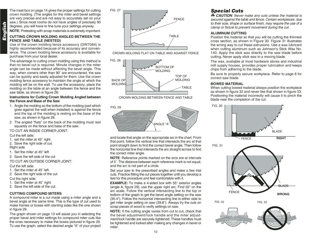
Position the material so that you will be cutting the thinnest cross section, as shown in Figure 30. Figure 31 illustrates the wrong way to cut these extrusions. Use a wax lubricant when cutting aluminum such as Johnson’s Stick Wax No.
140.Apply the stick wax directly to the saw blade before cutting. Never apply stick wax to a moving blade.
The wax, available at most hardware stores and industrial mill supply houses, provides proper lubrication and keeps chips from adhering to the blade.
Be sure to properly secure workpiece. Refer to page 6 for correct saw blade.
BOWED MATERIAL
When cutting bowed material always position the workpiece as shown in figure 32 and never like that shown in figure 33. Positioning the material incorrectly will cause it to pinch the blade near the completion of the cut.
FIG. 30
BLADE
![]() FENCERIGHT
FENCERIGHT
Right side | |
1. | Set the miter at 45° left |
2. | Save the left side of the cut |
TO CUT AN OUTSIDE CORNER JOINT: | |
Cut the left side:
1.Set the miter at 45˚ left.
2.Save the right side of the cut
Cut the right side:
1.Set the miter at 45˚ right.
2.Save the left side of the cut.
CUTTING COMPOUND MITERS
point straight down to find the correct bevel angle. Then follow the horizontal line that intersects the arc straight across to find the correct miter angle.
NOTE: Reference points marked on the arcs are at intervals of 5˚. The distance between each reference mark is not equal, and the arc is not part of a circle.
Set your saw to the prescribed angles and make a few trial cuts. Practice fitting the cut pieces together until you develop a feel for this procedure and feel comfortable with it.
EXAMPLE: To make a
FIG. 31
FENCE
BLADE
WRONG
A compound miter is a cut made using a miter angle and a bevel angle at the same time. This is the type of cut used to make frames or boxes with slanting sides like the one shown in figure 29.
The graph shown on page 13 will assist you in selecting the proper bevel and miter settings for compound miter cuts like the ones necessary to make the boxes pictured in figure 29. To use the graph, select the desired angle “A” of your project
(35.4°). Follow the horizontal intersecting line to either side to get miter angle setting on saw (29.8°). Always try the cuts on scrap pieces of wood to verify settings on saw.
NOTE: If the cutting angle varies from cut to cut, check that the bevel adjustment/lock handle and the miter adjust- ment/lock handle are securely tightened. These handles must be tightened and locked after making any changes in bevel or miter.
FIG. 32 | FIG. 33 | ||
|
|
|
|
12