TAILSTOCK LIVE CENTER
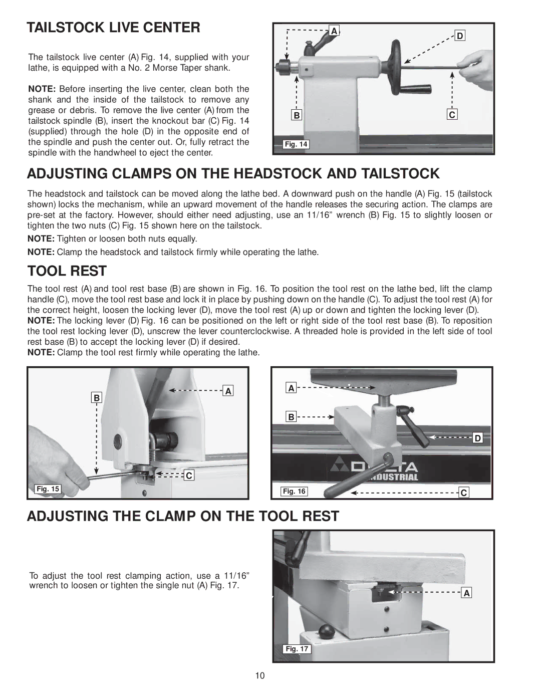
The tailstock live center (A) Fig. 14, supplied with your lathe, is equipped with a No. 2 Morse Taper shank.
NOTE: Before inserting the live center, clean both the shank and the inside of the tailstock to remove any grease or debris. To remove the live center (A) from the tailstock spindle (B), insert the knockout bar (C) Fig. 14 (supplied) through the hole (D) in the opposite end of the spindle and push the center out. Or, fully retract the spindle with the handwheel to eject the center.
![]()
![]() A
A
B
Fig. 14
D
C
ADJUSTING CLAMPS ON THE HEADSTOCK AND TAILSTOCK
The headstock and tailstock can be moved along the lathe bed. A downward push on the handle (A) Fig. 15 (tailstock shown) locks the mechanism, while an upward movement of the handle releases the securing action. The clamps are
NOTE: Tighten or loosen both nuts equally.
NOTE: Clamp the headstock and tailstock firmly while operating the lathe.
TOOL REST
The tool rest (A) and tool rest base (B) are shown in Fig. 16. To position the tool rest on the lathe bed, lift the clamp handle (C), move the tool rest base and lock it in place by pushing down on the handle (C). To adjust the tool rest (A) for the correct height, loosen the locking lever (D), move the tool rest (A) up or down and tighten the locking lever (D).
NOTE: The locking lever (D) Fig. 16 can be positioned on the left or right side of the tool rest base (B). To reposition the tool rest locking lever (D), unscrew the lever counterclockwise. A threaded hole is provided in the left side of tool rest base (B) to accept the locking lever (D) if desired.
NOTE: Clamp the tool rest firmly while operating the lathe.
B
Fig. 15
![]()
![]() A
A
![]()
![]() C
C
A ![]()
![]()
B ![]()
![]()
![]()
![]() D
D
Fig. 16 |
| C |
|
|
|
ADJUSTING THE CLAMP ON THE TOOL REST
To adjust the tool rest clamping action, use a 11/16” wrench to loosen or tighten the single nut (A) Fig. 17.
![]()
![]()
![]() A
A
Fig. 17
10