Installation
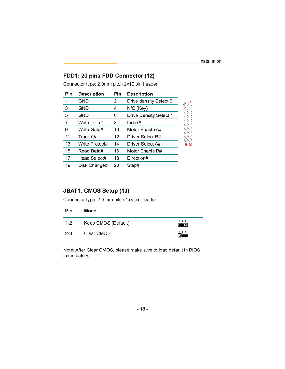
FDD1: 20 pins FDD Connector (12)
Connector type: 2.0mm pitch 2x10 pin header
Pin | Description | Pin | Description |
|
|
|
|
1 | GND | 2 | Drive density Select 0 |
|
|
|
|
3 | GND | 4 | N/C (Key) |
|
|
|
|
5 | GND | 6 | Drive Density Select 1 |
|
|
|
|
7 | Write Data# | 8 | Index# |
|
|
|
|
9 | Write Gate# | 10 | Motor Enable A# |
|
|
|
|
11 | Track 0# | 12 | Driver Select B# |
|
|
|
|
13 | Write Protect# | 14 | Driver Select A# |
|
|
|
|
15 | Read Data# | 16 | Motor Enable B# |
|
|
|
|
17 | Head Select# | 18 | Direction# |
|
|
|
|
19 | Disk Change# | 20 | Step# |
12
19 02![]()
JBAT1: CMOS Setup (13)
Connector type: 2.0 mm pitch 1x3 pin header.
Pin Mode
1 2 3
1 2 3
Note: After Clear CMOS, please make sure to load default in BIOS immediately.
- 18 -
