Manuals
/
Digital Data Communications
/
Photography
/
Security Camera
Digital Data Communications
FCS-4300 CAS-4000B ceiling mount kit, CAS-4000C corner mount kit
Models:
FCS-4100
FCS-4000
FCS-4300
1
13
93
93
Download
93 pages
27.18 Kb
10
11
12
13
14
15
16
17
<
>
Troubleshooting
Install
Warranty
Configuration of Main Console
Aim the camera plug to the bottom socket to connecting
Preset Position
ID address setup
The assembly completed CAS-4000D pole mount kit
Factory Default
For the alarm cable
Page 13
Image 13
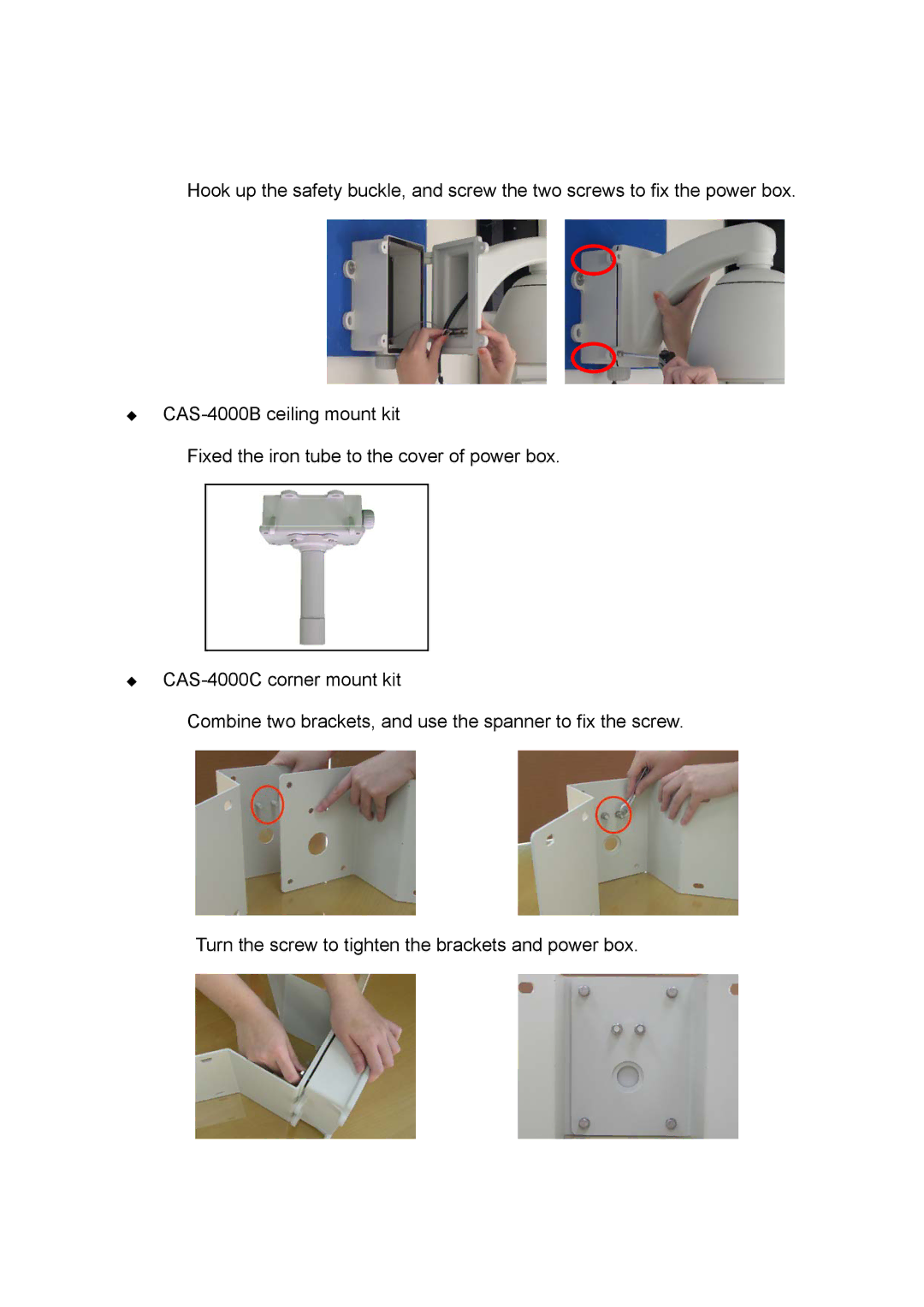
Hook up the safety buckle, and screw the two screws to fix the power box.
CAS-4000B
ceiling mount kit
Fixed the iron tube to the cover of power box.
CAS-4000C
corner mount kit
Combine two brackets, and use the spanner to fix the screw.
Turn the screw to tighten the brackets and power box.
Page 12
Page 14
Page 13
Image 13
Page 12
Page 14
Contents
User Manual
LevelOne
Ver2.1.0-0804
Before You Use This Product
2. Please don’t place the product on unstable desk or bracket
1. All operation please refer to the instruction
GNU GENERAL PUBLIC LICENSE
Table of Contents
Preset position set up and recall
Package Contents
Functions and Operation directory
Pan/Tilt/Zoom
Users can press the zoom button to adjust the image viewing distance
Focusing control
Iris control
Installation Notice
Hardware Installation
FCS-4300/4400/4500Housing installation
FCS-4000/4100/4200Housing installation
For the alarm cable
unscrew the bottom screw to install cables
ID address setup
Camera installation
Remarks Please reboot the camera after the camera setup is done
Remarks Please reboot the camera after the protocol setup is done
Protocol setup
Alarm Dip-switchers
Aim the camera plug to the bottom socket to connecting
Bracket installation
Turn the screw to tighten the brackets and power box
Fixed the iron tube to the cover of power box
CAS-4000B ceiling mount kit
CAS-4000C corner mount kit
Fixed the bracket on the rear of power box
The assembly completed CAS-4000D pole mount kit
The assembly will be done after the stainless ring is hooped
Install “IP CamLocator”
Software Installation
Install “IP CamSecure” Click”Install Software”
Custom Setup Type
Configuration of Main Console
How to Use IP CamLocator
Main Menu
Initial use IP Cam Locator
User
Main Menu Camera
About
Camera
Setup
Page
Page
Page
Page
DDNS settings You can change the DDNS settings here
Apply settings Click on “Apply” to use the new settings
Upgrade
Factory Default
Click on “OK” to continue. The device will automatically reboot
Reboot
User
Note Configuration file format is *.conf
Page
Info
User
Mode:Set a user to Admin, Operator or Viewer mode
Username:Set a user name between 5 and 16 characters
Date/Time
TCP/IP
DNS Setting
Note:
IP Address
Page
PPPoE
Note:
DDNS
Note:
About
Initial accessing the network camera
How to Access to the Network Camera
Setting
Configuration of Main Console Language
Client Setting
Image Setup
Pan / Tilt control
Digital Zoom in / out the image via the monitor window
Live View
Note:
:Pause the current video :Stop the current video
cameras via the Ethernet using your microphone. Video play buttons
:Play the video :Record the current video
System
Basic Setting
Information
Initialize
Day & Time
Page
General
Camera
Note:
Note:
MPEG4 Computer View
RTP If RTSP mode is ON Unicast streaming
RTSP If RTSP mode is ON
Multicast streaming
Multicast address Specify the multicast server address
Mobile View
Time-To-Live Set the maximum TTL that multicast can pass through
11000. Specify an even number from 1024 to
Image Size The Image size of Mobile view is fixed at
Quality
Note:
MJPEG
Information
Network
Note:
follows
PPPoE
DDNS
UPnP
IP Notification
Page
Account
Security
HTTPS
PTZ Control
Advance
Setting
Setting
Preset Position
Set:Use it to save the camera position to a preset number
preset position setting
General
Patrol
Tour position
4. Follow the steps to set the other orders
3. Click the SET. The tour position is saved
5. Click the OK to save the tour
Alarm sending
FTP Client
General
Note:
Note:
Suffix:Select a suffix to add to the file name
Periodical sending
General
SMTP
Note:
Attached File Type Select to attach the file as JPEG or MPEG4
followings
Alarm sending
the Alarm Buffer - Alarm buffer setting Menu on page
Periodical sending
HTTP Event
General
sensor input or with the built-in motion detection function to HTTP server. HTTP client setting menu is composed of two tabs, General and Alarm sending
Note:
Alarm sending
Setting
Schedule
Setting
Alarm Input
Setting
Alarm Buffer
Motion Detection
Note:
A detecting zone 1 appears and use mouse to adjust and move the zone boundaries and position. Use tool bar to set Threshold and Sensitivity value
System Log
Solutions
Trouble shooting sheet
system after power on
Troubles
1/4 Exview HAD CCD
Technical Parameters
Preamble
GNU GENERAL PUBLIC LICENSE
Terms And Conditions For Copying, Distribution And Modification
GNU GENERAL PUBLIC LICENSE
Page
Page
Page
REPAIR OR CORRECTION
NO WARRANTY