 Fireplace Installation
4.Take the cables out from the junction box, loosen the two wire twist nuts and remove the cord set (Figure 2).
5.Route the power supply wire through the knockout on supplied alternative junction box cover and secure with a wire clamp (not supplied) (Figure 3).
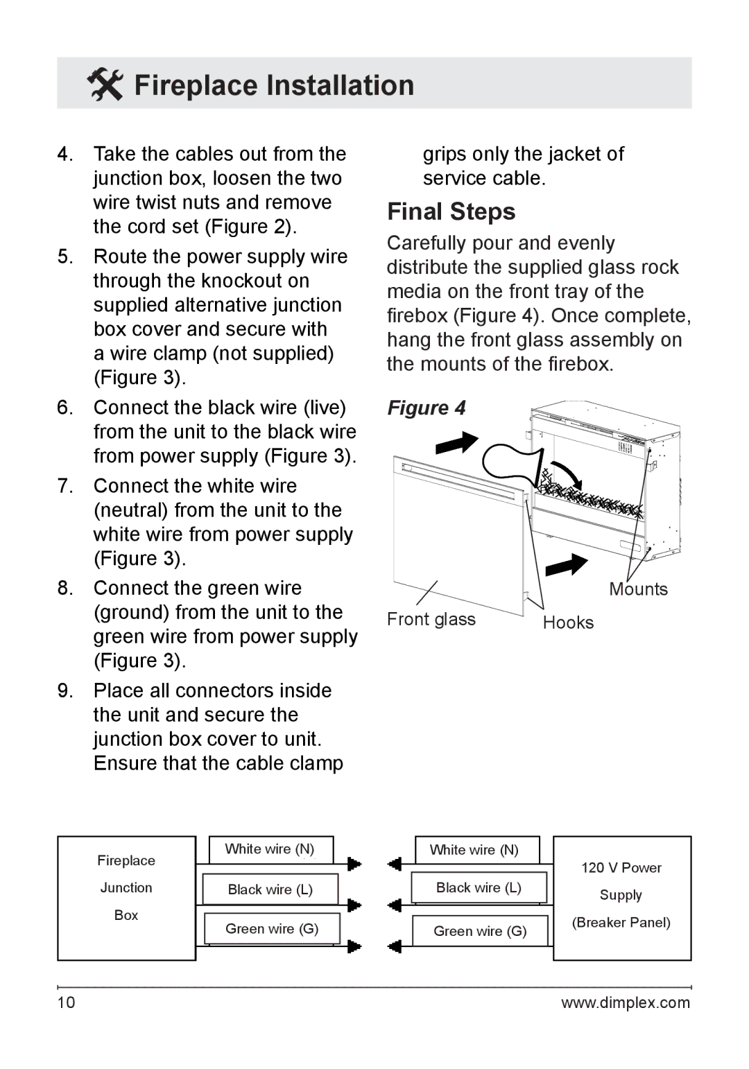
6.Connect the black wire (live) from the unit to the black wire from power supply (Figure 3).
7.Connect the white wire (neutral) from the unit to the white wire from power supply (Figure 3).
8.Connect the green wire (ground) from the unit to the green wire from power supply (Figure 3).
9.Place all connectors inside the unit and secure the junction box cover to unit. Ensure that the cable clamp
grips only the jacket of service cable.
Final Steps
Carefully pour and evenly distribute the supplied glass rock media on the front tray of the firebox (Figure 4). Once complete, hang the front glass assembly on the mounts of the firebox.
Figure 4
Mounts
Front glass | Hooks |
Fireplace
Junction
Box
White wire (N)
Black wire (L)
Green wire (G)
White wire (N)
Black wire (L)
Green wire (G)
120 V Power
Supply
(Breaker Panel)
10 | www.dimplex.com |
