
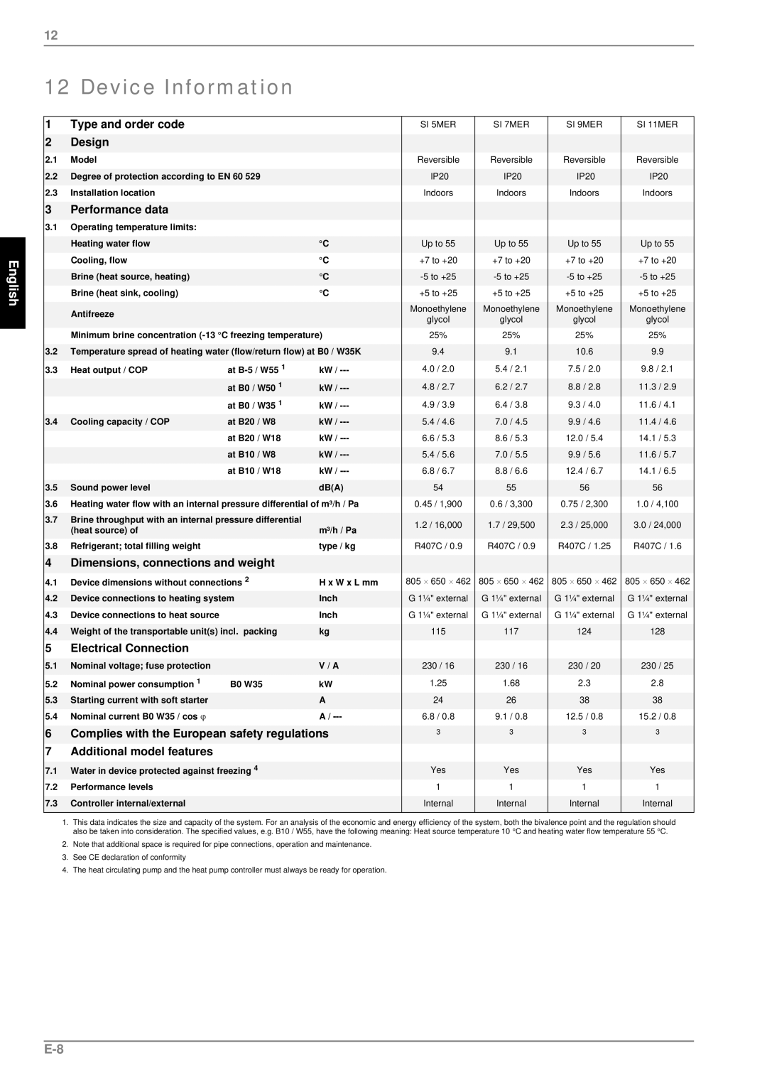
SI7MER, SI 11MER, SI 9MER, SI 5MER specifications
The Dimplex SI series is an impressive range of high-performance electric storage heaters designed for modern living while prioritizing energy efficiency and comfort. This line includes models SI 5MER, SI 7MER, SI 9MER, and SI 11MER, each tailored to meet various heating needs and room sizes.One of the standout features of the Dimplex SI series is its innovative storage technology. These heaters work by storing heat during off-peak hours, when electricity costs are lower, and releasing it throughout the day. This characteristic not only helps in reducing energy bills but also provides a stable and comfortable heat output regardless of external temperature fluctuations.
The SI 5MER model is designed for smaller spaces, providing an efficient heating solution for apartments or compact rooms. The digital controls allow users to set desired temperatures easily, while the advanced thermal insulation minimizes heat loss.
Moving to the SI 7MER, this model offers a higher output suitable for slightly larger areas. It incorporates similar technology and features as the SI 5MER but with increased heat retention capacity, ensuring that spaces remain warm during colder months.
The SI 9MER takes performance up a notch, catering to medium-sized rooms. It includes a larger storage capacity and enhanced insulation, ensuring that warmth is dissipated gradually and evenly throughout the day. The integrated digital display allows for precise control, enhancing user convenience.
For those requiring even more power, the SI 11MER is the ideal option. It is perfect for larger living spaces and features advanced energy efficiency technologies. With a robust design, this model not only functions effectively but also features a sleek and modern aesthetic that can complement any interior.
All models in the Dimplex SI series are constructed with a focus on user-friendliness and safety. They are fitted with features such as overheat protection and child safety locks, ensuring peace of mind for households with children.
In summary, the Dimplex SI series—comprising the SI 5MER, SI 7MER, SI 9MER, and SI 11MER—is a versatile and efficient choice for electric heating. Each model is built with innovative technology, ensuring effective heat storage and release while maintaining energy efficiency. With a focus on safety and ease of use, these heaters are well-suited to adapt to modern lifestyle demands.