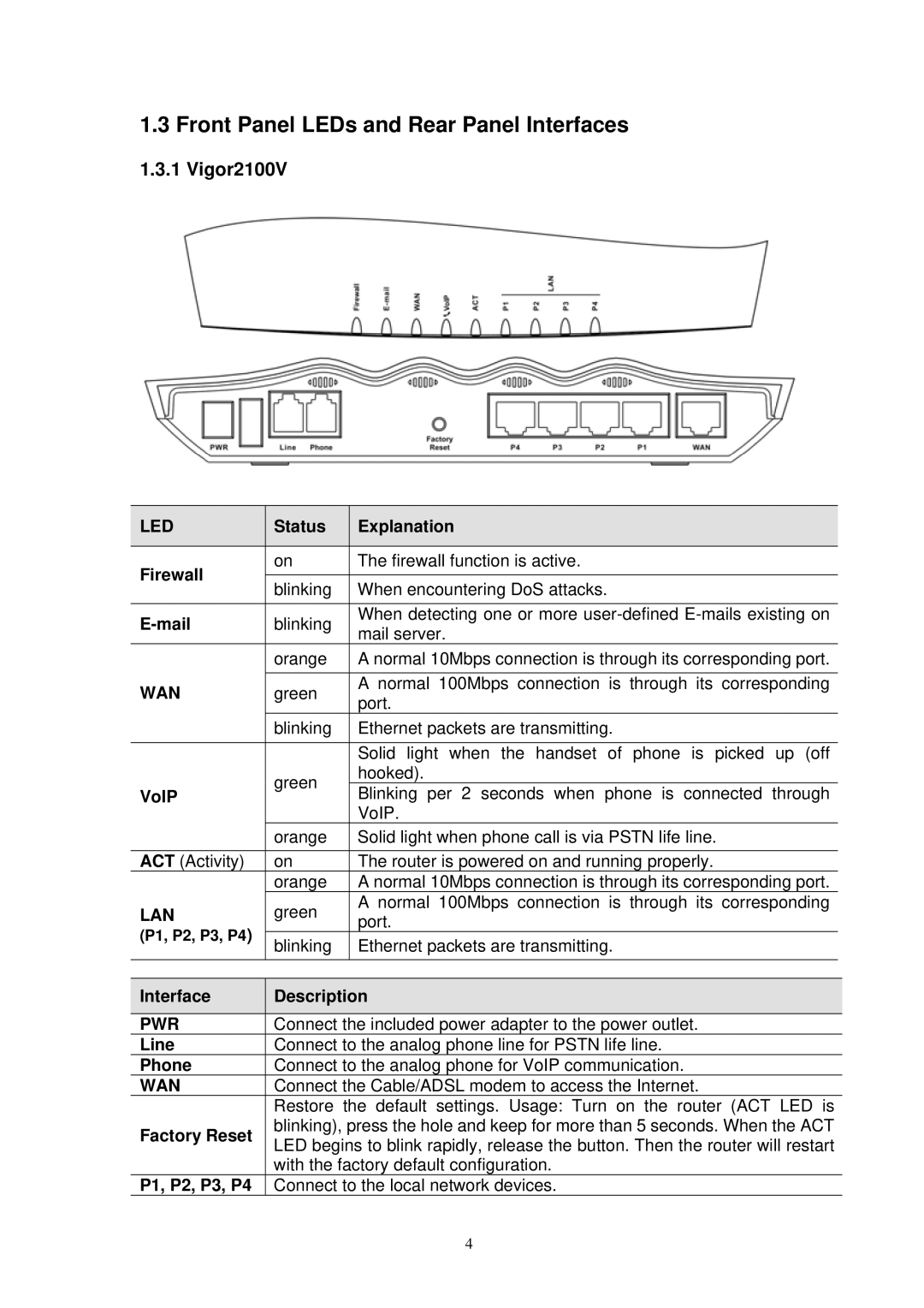
1.3 Front Panel LEDs and Rear Panel Interfaces
1.3.1 Vigor2100V
| LED |
|
| Status |
|
| Explanation |
|
|
|
|
|
|
|
|
| Firewall |
|
| on |
|
| The firewall function is active. |
|
|
|
|
|
|
| |
|
|
| blinking |
| When encountering DoS attacks. | ||
|
|
|
|
| |||
|
|
|
|
|
|
|
|
|
|
|
| blinking |
|
| When detecting one or more |
|
|
|
|
| mail server. | ||
|
|
|
|
|
|
| |
|
|
|
| orange |
|
| A normal 10Mbps connection is through its corresponding port. |
|
|
|
|
|
|
|
|
| WAN |
|
| green |
|
| A normal 100Mbps connection is through its corresponding |
|
|
|
|
| port. | ||
|
|
|
|
|
|
| |
|
|
|
| blinking |
|
| Ethernet packets are transmitting. |
|
|
|
|
|
|
|
|
|
|
|
|
|
|
| Solid light when the handset of phone is picked up (off |
|
|
|
| green |
|
| hooked). |
| VoIP |
|
|
|
| Blinking per 2 seconds when phone is connected through | |
|
|
|
|
|
| ||
|
|
|
|
|
|
| VoIP. |
|
|
|
| orange |
|
| Solid light when phone call is via PSTN life line. |
|
|
|
|
|
|
|
|
| ACT (Activity) |
|
| on |
|
| The router is powered on and running properly. |
|
|
|
| orange |
|
| A normal 10Mbps connection is through its corresponding port. |
| LAN |
|
| green |
|
| A normal 100Mbps connection is through its corresponding |
|
|
|
|
| port. | ||
| (P1, P2, P3, P4) |
|
|
|
|
|
|
|
|
| blinking |
|
| Ethernet packets are transmitting. | |
|
|
|
|
|
| ||
|
|
|
|
|
|
|
|
| Interface |
|
| Description |
|
|
|
|
|
| PWR |
|
| Connect the included power adapter to the power outlet. |
| Line |
|
| Connect to the analog phone line for PSTN life line. |
| Phone |
|
| Connect to the analog phone for VoIP communication. |
| WAN |
|
| Connect the Cable/ADSL modem to access the Internet. |
|
|
|
| Restore the default settings. Usage: Turn on the router (ACT LED is |
| Factory Reset |
|
| blinking), press the hole and keep for more than 5 seconds. When the ACT |
|
|
| LED begins to blink rapidly, release the button. Then the router will restart | |
|
|
|
| |
|
|
|
| with the factory default configuration. |
| P1, P2, P3, P4 | Connect to the local network devices. | ||
|
| 4 | ||
