from turning and tighten the socket head screw(B) with the 3/16" hex wrench.
4.With the support plate level, try moving the table up and down.
5.If the movement is still tight, go back through this procedure before going to the next step of CHECKING
LOCK NUT ADJUSTMENT.
STEP 3 - CHECKING LOCK NUT ADJUSTMENT
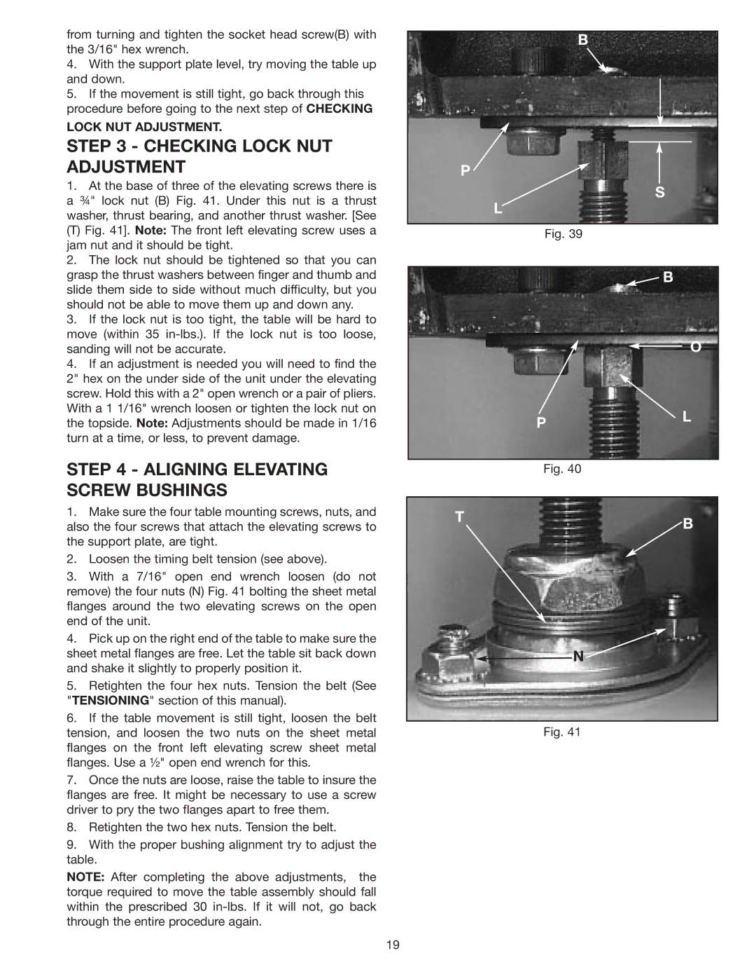
1.At the base of three of the elevating screws there is a ¾" lock nut (B) Fig. 41. Under this nut is a thrust washer, thrust bearing, and another thrust washer. [See
(T) Fig. 41]. Note: The front left elevating screw uses a jam nut and it should be tight.
2.The lock nut should be tightened so that you can grasp the thrust washers between finger and thumb and slide them side to side without much difficulty, but you should not be able to move them up and down any.
3.If the lock nut is too tight, the table will be hard to move (within 35
4.If an adjustment is needed you will need to find the 2" hex on the under side of the unit under the elevating screw. Hold this with a 2" open wrench or a pair of pliers. With a 1 1/16" wrench loosen or tighten the lock nut on the topside. Note: Adjustments should be made in 1/16 turn at a time, or less, to prevent damage.
STEP 4 - ALIGNING ELEVATING SCREW BUSHINGS
1.Make sure the four table mounting screws, nuts, and also the four screws that attach the elevating screws to the support plate, are tight.
2.Loosen the timing belt tension (see above).
3.With a 7/16" open end wrench loosen (do not remove) the four nuts (N) Fig. 41 bolting the sheet metal flanges around the two elevating screws on the open end of the unit.
4.Pick up on the right end of the table to make sure the sheet metal flanges are free. Let the table sit back down and shake it slightly to properly position it.
5.Retighten the four hex nuts. Tension the belt (See "TENSIONING" section of this manual).
6.If the table movement is still tight, loosen the belt tension, and loosen the two nuts on the sheet metal flanges on the front left elevating screw sheet metal flanges. Use a ½" open end wrench for this.
7.Once the nuts are loose, raise the table to insure the flanges are free. It might be necessary to use a screw driver to pry the two flanges apart to free them.
8.Retighten the two hex nuts. Tension the belt.
9.With the proper bushing alignment try to adjust the table.
NOTE: After completing the above adjustments, the torque required to move the table assembly should fall within the prescribed 30
B
P
S
L
Fig. 39
![]() B
B
O
PL
Fig. 40
TB
![]() N
N![]()
Fig. 41
19