TABLE MOVEMENT TROUBLESHOOTING GUIDE
In the event your table will not adjust properly, or is tight when adjusting up and down, or the timing belt is jumping teeth, this guide provides the information necessary to realign the table mechanism and adjust the belt tension.
![]() DISCONNECT THE MACHINE FROM POWER SOURCE BEFORE SERVICING, MAKING REPAIRS, OR WHEN CHANGING ACCESSORIES.
DISCONNECT THE MACHINE FROM POWER SOURCE BEFORE SERVICING, MAKING REPAIRS, OR WHEN CHANGING ACCESSORIES.
The Drum Sander feed table should adjust up or down with 35
STEP 1 - TENSION ON TIMING BELT
1.The timing belt should be checked for the correct tension. If the belt is too tight, the table will be difficult to move. A loose timing belt may cause the belt to jump a tooth on the timing gear. Deflection in the middle of the long span should be 2 - 3 lbs to deflect the belt to the outside frame wall.
2.To adjust the timing belt tension, first loosen the tension. To do this, find one of the timing belt idler rollers under the right hand end of the unit between the timing gears, and with a ½" wrench loosen the screw (the nut for this screw can be seen on the topside of the base).
![]() Do not rotate
Do not rotate
3.With the ½" wrench still on the idler screw under the unit, push the slack of the belt toward the column end of
the unit, and tighten the screw. ![]() Be careful not to
Be careful not to
4. With the proper belt tension try to adjust the table.
W
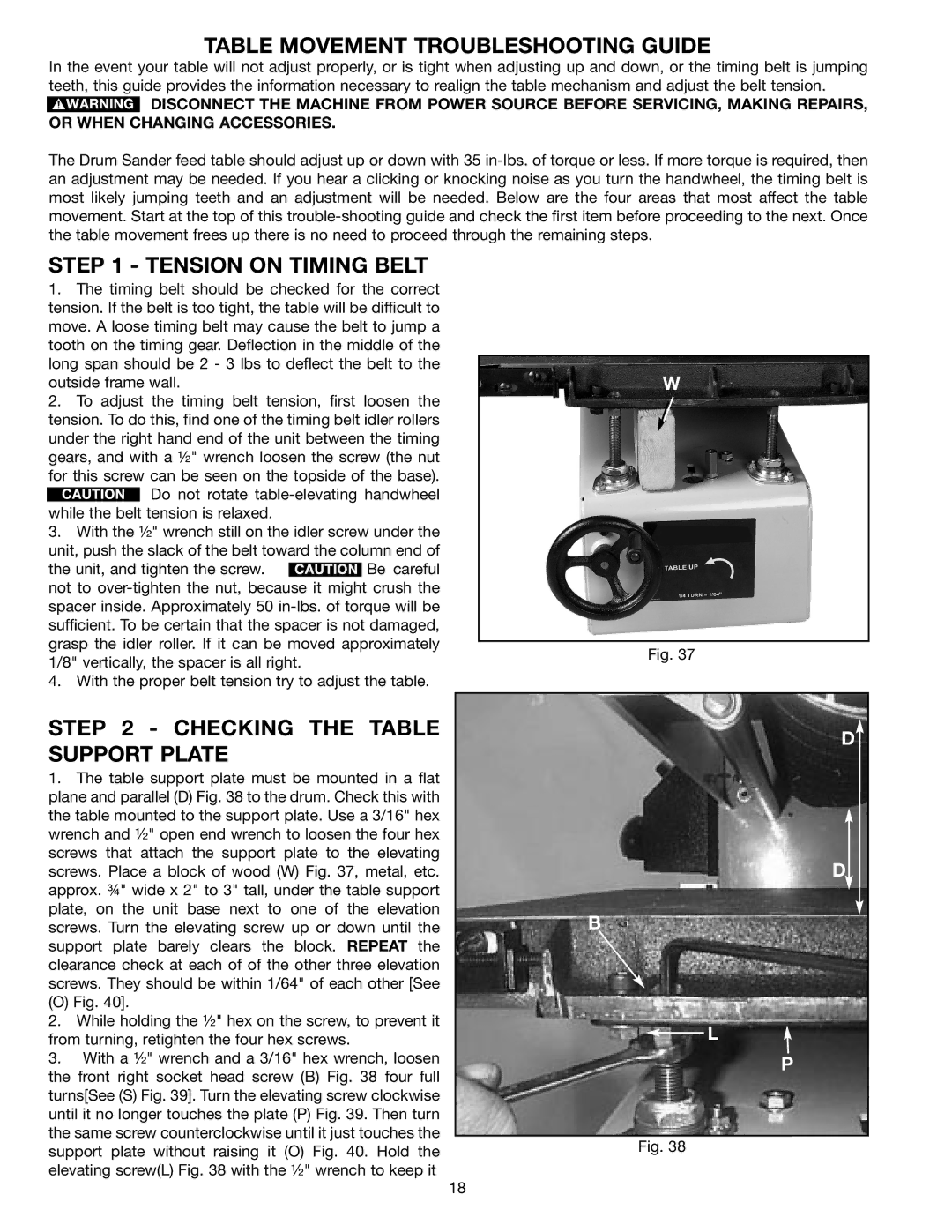
Fig. 37
STEP 2 - CHECKING THE TABLE SUPPORT PLATE
1.The table support plate must be mounted in a flat plane and parallel (D) Fig. 38 to the drum. Check this with the table mounted to the support plate. Use a 3/16" hex wrench and ½" open end wrench to loosen the four hex screws that attach the support plate to the elevating screws. Place a block of wood (W) Fig. 37, metal, etc. approx. ¾" wide x 2" to 3" tall, under the table support plate, on the unit base next to one of the elevation screws. Turn the elevating screw up or down until the support plate barely clears the block. REPEAT the clearance check at each of of the other three elevation screws. They should be within 1/64" of each other [See
(O) Fig. 40].
2.While holding the ½" hex on the screw, to prevent it from turning, retighten the four hex screws.
3.With a ½" wrench and a 3/16" hex wrench, loosen the front right socket head screw (B) Fig. 38 four full turns[See (S) Fig. 39]. Turn the elevating screw clockwise until it no longer touches the plate (P) Fig. 39. Then turn the same screw counterclockwise until it just touches the support plate without raising it (O) Fig. 40. Hold the elevating screw(L) Fig. 38 with the ½" wrench to keep it
D
D
B
![]() L
L
P
Fig. 38
18
