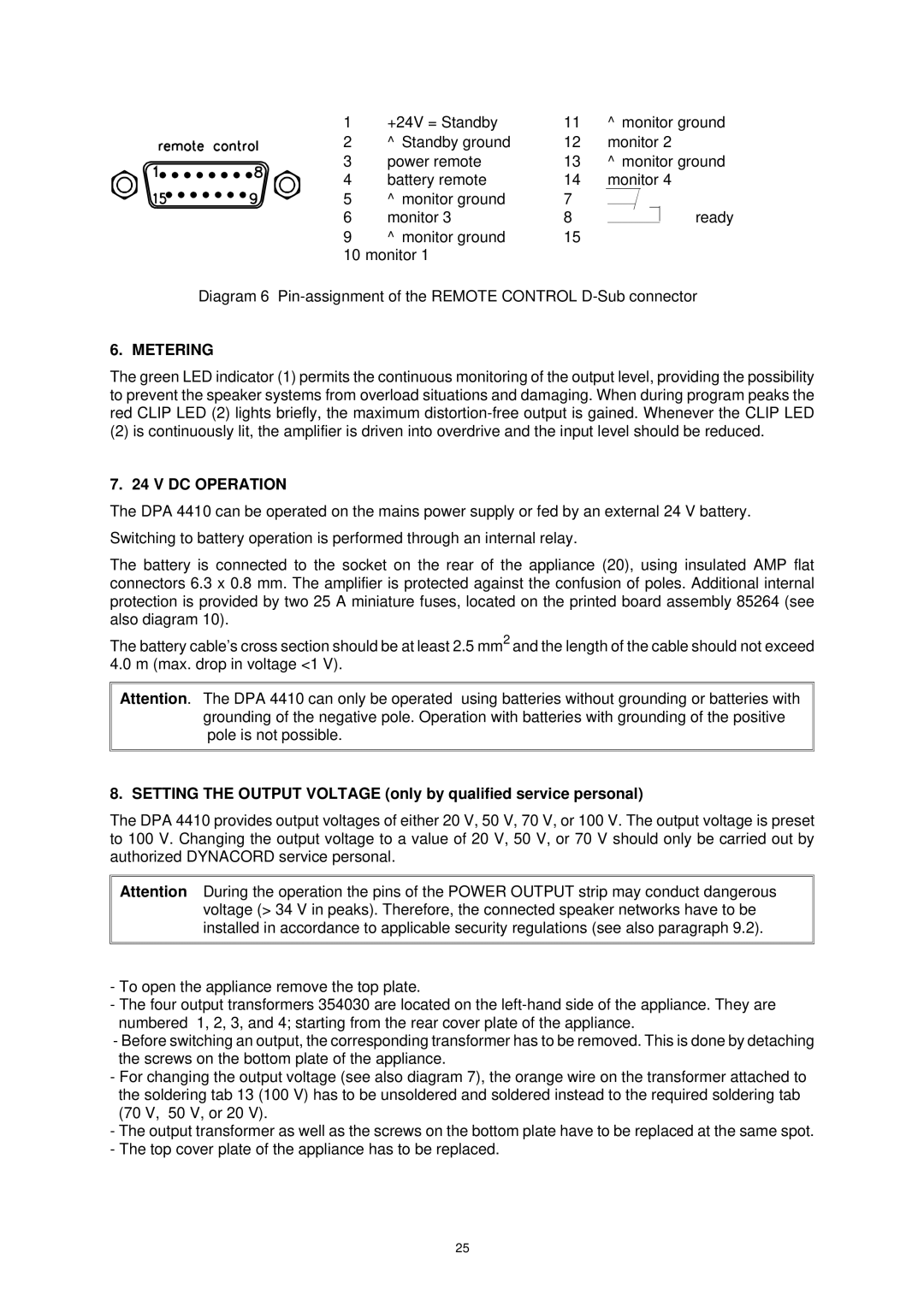
1 | +24V = Standby | 11 | ⊥ monitor ground |
2 | ⊥ Standby ground | 12 | monitor 2 |
3 | power remote | 13 | ⊥ monitor ground |
4 | battery remote | 14 | monitor 4 |
5 | ⊥ monitor ground | 7 |
|
6 | monitor 3 | 8 | ready |
9 | ⊥ monitor ground | 15 |
|
10 monitor 1
Diagram 6
6. METERING
The green LED indicator (1) permits the continuous monitoring of the output level, providing the possibility to prevent the speaker systems from overload situations and damaging. When during program peaks the red CLIP LED (2) lights briefly, the maximum
(2) is continuously lit, the amplifier is driven into overdrive and the input level should be reduced.
7. 24 V DC OPERATION
The DPA 4410 can be operated on the mains power supply or fed by an external 24 V battery.
Switching to battery operation is performed through an internal relay.
The battery is connected to the socket on the rear of the appliance (20), using insulated AMP flat connectors 6.3 x 0.8 mm. The amplifier is protected against the confusion of poles. Additional internal protection is provided by two 25 A miniature fuses, located on the printed board assembly 85264 (see also diagram 10).
The battery cable’s cross section should be at least 2.5 mm2 and the length of the cable should not exceed 4.0 m (max. drop in voltage <1 V).
Attention. The DPA 4410 can only be operated using batteries without grounding or batteries with grounding of the negative pole. Operation with batteries with grounding of the positive pole is not possible.
8. SETTING THE OUTPUT VOLTAGE (only by qualified service personal)
The DPA 4410 provides output voltages of either 20 V, 50 V, 70 V, or 100 V. The output voltage is preset to 100 V. Changing the output voltage to a value of 20 V, 50 V, or 70 V should only be carried out by authorized DYNACORD service personal.
Attention During the operation the pins of the POWER OUTPUT strip may conduct dangerous voltage (> 34 V in peaks). Therefore, the connected speaker networks have to be installed in accordance to applicable security regulations (see also paragraph 9.2).
-To open the appliance remove the top plate.
-The four output transformers 354030 are located on the
-Before switching an output, the corresponding transformer has to be removed. This is done by detaching the screws on the bottom plate of the appliance.
-For changing the output voltage (see also diagram 7), the orange wire on the transformer attached to the soldering tab 13 (100 V) has to be unsoldered and soldered instead to the required soldering tab (70 V, 50 V, or 20 V).
-The output transformer as well as the screws on the bottom plate have to be replaced at the same spot.
-The top cover plate of the appliance has to be replaced.
25