DIGITAL SYSTEM AMPLIFIER
2 Installation
2.1 Controls, Indicators and Connections
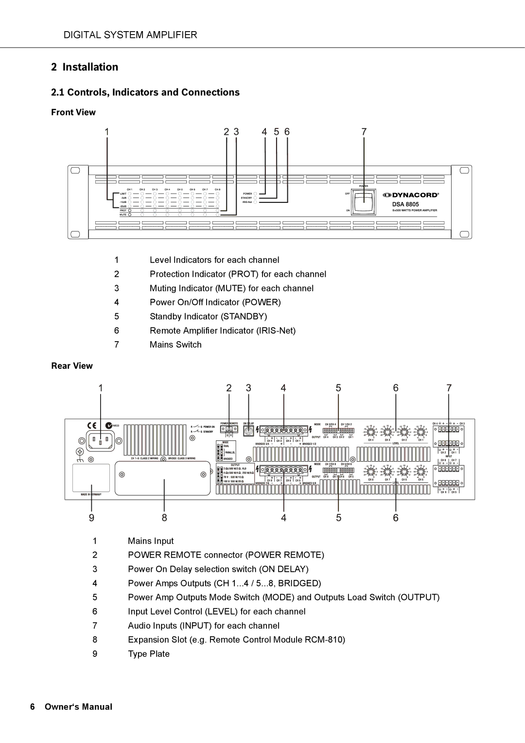
Front View
1Level Indicators for each channel
2Protection Indicator (PROT) for each channel
3Muting Indicator (MUTE) for each channel
4Power On/Off Indicator (POWER)
5Standby Indicator (STANDBY)
6Remote Amplifier Indicator
7Mains Switch
Rear View
1Mains Input
2POWER REMOTE connector (POWER REMOTE)
3Power On Delay selection switch (ON DELAY)
4Power Amps Outputs (CH 1...4 / 5...8, BRIDGED)
5Power Amp Outputs Mode Switch (MODE) and Outputs Load Switch (OUTPUT)
6Input Level Control (LEVEL) for each channel
7Audio Inputs (INPUT) for each channel
8Expansion Slot (e.g. Remote Control Module
9Type Plate