Dynacord DSA 8405, DSA 8410, DSA 8805 owner manual Data rate of the can bus is preset to 10 kbit/s

Models: DSA 8410 DSA 8805 DSA 8405

1 40
Download 40 pages 8.98 Kb
Page 17
Image 17

DIGITAL SYSTEM AMPLIFIER

3 STATUS LED

The STATUS LED is for monitoring the communication on the CAN bus. The LED blinks rhythmically every 3 seconds, when the module’s address is set to “00“, which means that it is disconnected from the CAN bus and software control. The LED blinks rhythmically in intervals of one second, when an address in the range of 01 to 250 has been assigned to the module and there has not yet been any activity on the CAN bus. As soon as communication on the CAN bus is recognized, the LED lights for at least 100 ms, when the power amplifier sends data on the CAN bus.

4 REMOTE CAN BUS Connection

The RCM-810 module provides two RJ-45 sockets for connecting to the REMOTE CAN BUS. These sockets are connected in parallel and serve as inputs as well as for daisy-chaining the devices on the remote network. Cabling in a rack system can be established using commercially available RJ-45 network cables. However, CAN guidelines have to be observed for longer cable lengths. Both ends of the CAN bus must be terminated using 120 Ω terminating plugs.

The CAN bus allows using different data rates, whereas the data rate is inversely proportional to the bus length. For smaller network setups, data rates can be as high as 500 kbit/s. For broader networks, reducing the data rate becomes necessary (down to the minimum data rate of 10 kbit/s).

NOTE:

The data rate of the CAN bus is preset to 10 kbit/s.

The following table illustrates the relation between data rate and bus length or network size. The use of CAN repeaters is strongly recommended for busses that exceed 1000 meters in length.

Transfer rate (in kbit/s)

Bus length (in m)

500

100


250

250


125

500


62,5

1000


20

2500


10

5000


Table 4.3: Transfer rate and bus length
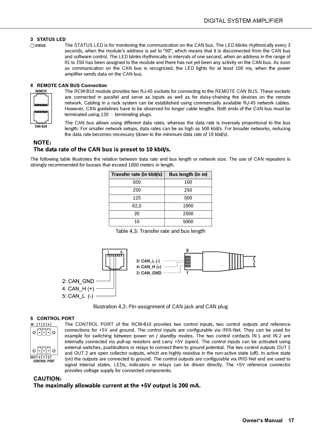
Illustration 4.2: Pin-assignment of CAN jack and CAN plug

5 CONTROL PORT

The CONTROL PORT of the RCM-810 provides two control inputs, two control outputs and reference connections for +5V and ground. The control inputs are configurable via IRIS-Net. They can be used for example for switching between power on / standby modes. The two control contacts IN 1 and IN 2 are internally connected via pull-up resistors and carry +5V (open). The control inputs can be activated using external switches, pushbuttons or relays to connect them to ground potential. The two control outputs OUT 1 and OUT 2 are open collector outputs, which are highly resistive in the non-active state (off). In active state (on) the outputs are connected to ground. The control outputs are configurable via IRIS-Net and are used to signal internal states. LEDs, indicators or relays can be driven directly. The +5V reference connector provides voltage supply for connected components.

CAUTION:

The maximally allowable current at the +5V output is 200 mA.

Owner‘s Manual 17

Page 17
Image 17
Dynacord DSA 8405 Data rate of the can bus is preset to 10 kbit/s, Maximally allowable current at the +5V output is 200 mA