DIGITAL SYSTEM AMPLIFIER
Controls and Connections
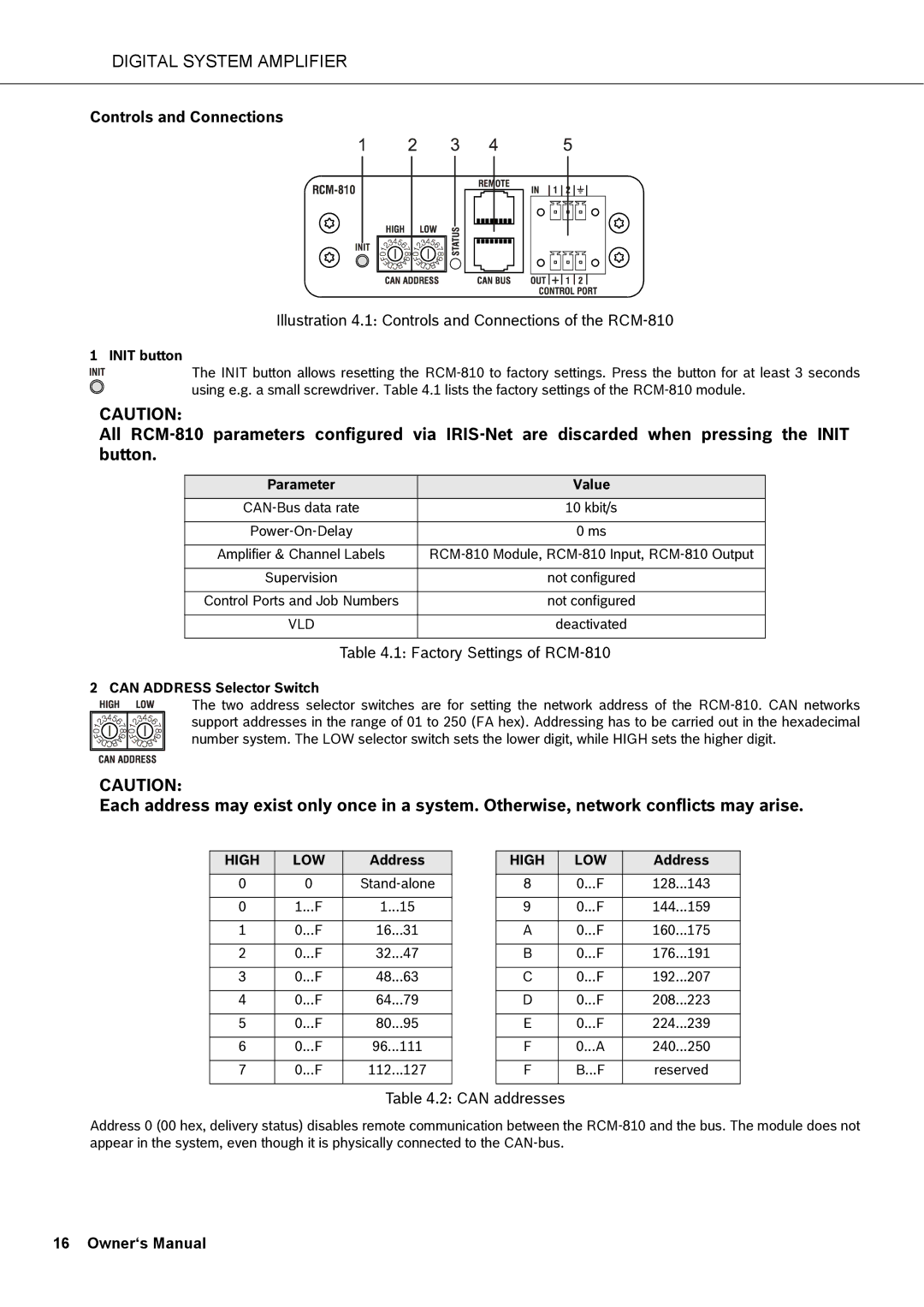
Illustration 4.1: Controls and Connections of the RCM-810
1 INIT button
The INIT button allows resetting the
CAUTION:
All
Parameter | Value |
10 kbit/s | |
|
|
0 ms | |
|
|
Amplifier & Channel Labels | |
|
|
Supervision | not configured |
|
|
Control Ports and Job Numbers | not configured |
|
|
VLD | deactivated |
|
|
Table 4.1: Factory Settings of RCM-810
2 CAN ADDRESS Selector Switch
The two address selector switches are for setting the network address of the
CAUTION:
Each address may exist only once in a system. Otherwise, network conflicts may arise.
HIGH | LOW | Address | ||
0 |
| 0 | ||
|
|
|
|
|
0 | 1... | F | 1... | 15 |
|
|
|
|
|
1 | 0... | F | 16... | 31 |
|
|
|
|
|
2 | 0... | F | 32... | 47 |
|
|
|
|
|
3 | 0... | F | 48... | 63 |
|
|
|
|
|
4 | 0... | F | 64... | 79 |
|
|
|
|
|
5 | 0... | F | 80... | 95 |
|
|
|
|
|
6 | 0... | F | 96... | 111 |
|
|
|
|
|
7 | 0... | F | 112... | 127 |
|
|
|
|
|
HIGH | LOW | Address | ||
8 | 0... | F | 128... | 143 |
|
|
|
|
|
9 | 0... | F | 144... | 159 |
|
|
|
|
|
A | 0... | F | 160... | 175 |
|
|
|
|
|
B | 0... | F | 176... | 191 |
|
|
|
|
|
C | 0... | F | 192... | 207 |
|
|
|
|
|
D | 0... | F | 208... | 223 |
|
|
|
|
|
E | 0... | F | 224... | 239 |
|
|
|
|
|
F | 0... | A | 240... | 250 |
|
|
|
| |
F | B... | F | reserved | |
|
|
|
|
|
Table 4.2: CAN addresses
Address 0 (00 hex, delivery status) disables remote communication between the
