SPI9000 specifications
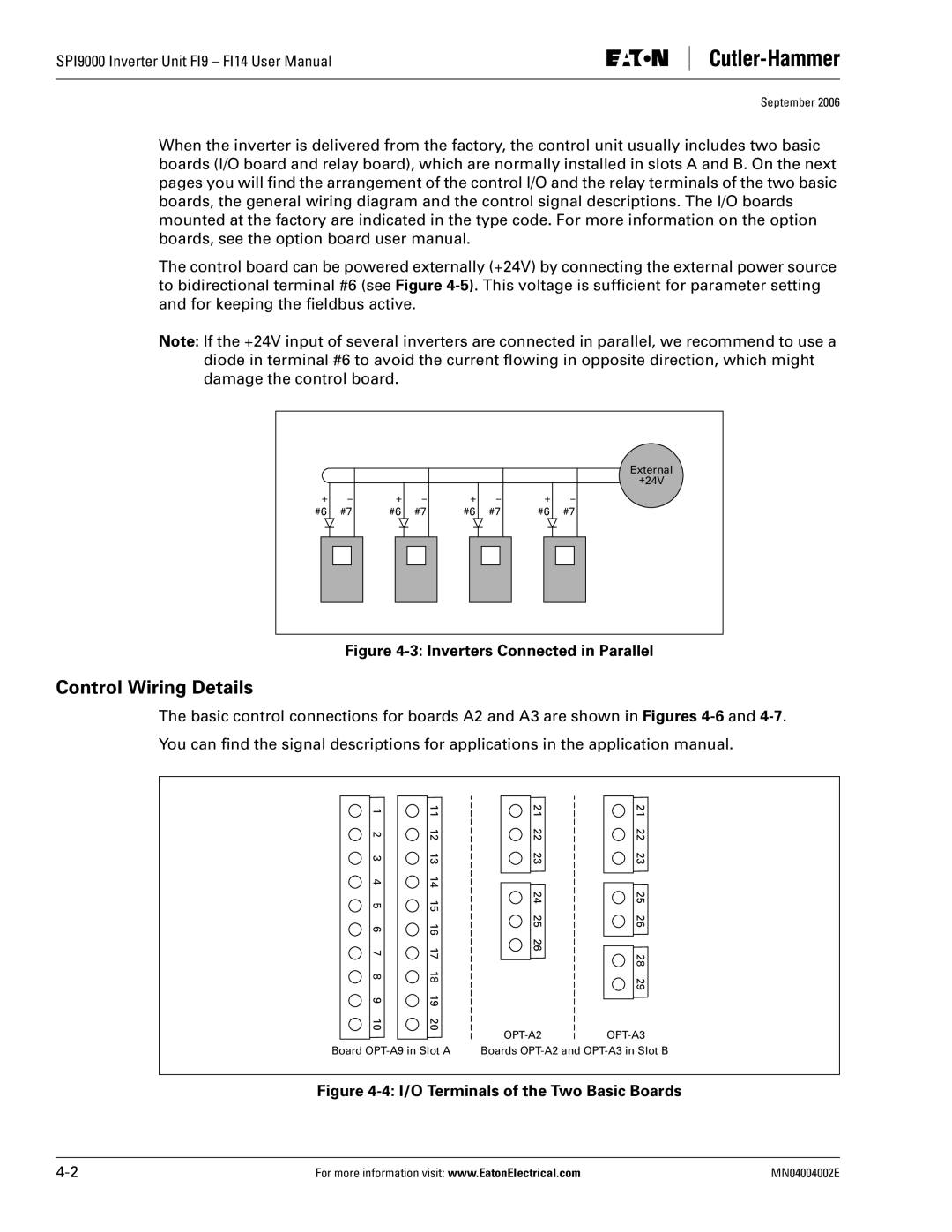
The Eaton Electrical SPI9000 is a cutting-edge power management system designed to enhance efficiency and reliability in electrical distribution. This state-of-the-art solution integrates advanced technologies to optimize performance, making it an ideal choice for various industrial and commercial applications.One of the standout features of the SPI9000 is its scalability. Businesses can easily adapt the system to meet their unique power needs, whether for a single facility or multiple sites. This flexibility is crucial in today's fast-paced environment, where operational demands can shift rapidly. The system is engineered to grow alongside your business, providing robust power management as requirements evolve.
At the heart of the SPI9000 is its intelligent monitoring capability. The system utilizes real-time data analytics to monitor energy consumption, detect anomalies, and predict maintenance needs. This proactive approach not only helps in reducing downtime but also cultivates a culture of energy efficiency within organizations. By leveraging insights derived from data, companies can make informed decisions that lead to significant cost savings.
The SPI9000 incorporates advanced communications technology, allowing seamless integration with existing building management systems. This interoperability is vital for creating smart grids and enhancing overall control of electrical networks. Additionally, the system supports various communication protocols, including Modbus, BACnet, and Ethernet, ensuring compatibility with a wide range of devices and applications.
Safety is paramount in any electrical system, and the SPI9000 excels in this regard. It features enhanced protective measures, including overcurrent protection, short-circuit protection, and arc flash detection, ensuring the safety of both personnel and equipment. These safety features not only safeguard investments but also contribute to creating a safer working environment.
Energy efficiency is another cornerstone of the SPI9000 design. The system is equipped with advanced power quality monitoring features, which help identify and mitigate issues related to harmonics, voltage sags, and swells. By maintaining optimal power quality, the SPI9000 ensures that equipment operates efficiently, extending its lifespan while reducing energy costs.
In summary, the Eaton Electrical SPI9000 is a versatile and efficient power management solution that brings together scalability, intelligent monitoring, advanced communication capabilities, enhanced safety features, and energy efficiency. Thanks to its innovative technologies and characteristics, the SPI9000 serves as an indispensable tool for modern businesses seeking to streamline their electrical operations and enhance their energy management strategies.

