1.Remove the back panel from one side of the enclosure by removing its 12 retaining screws.
2.Remove the amplifier module from the other side of the enclosure by removing its 12 retaining screws.
3.Pass the amplifier module through the openings in the enclosure and position it in place of the blank
panel. You may also disconnect the quick release connector and move the amplifier outside the enclosure, reconnecting it through the other opening.
4.NOTE: To keep the input and power cabling close to the floor when in use, rotate the panel so that the input connectors are adjacent to the rear "spine" of the enclosure.
5.Refasten both the blank panel and amplifier panels, securely tightening all screws.
5 . 3 | C o n f i g u r i n g A r r a y s |
NT loudspeakers can be arrayed in various ways. However, arraying loudspeakers requires special consideration for the overall array's mounting angle, projection pattern, rigging/mounting method, and for system tuning adjustments. These issues can be significantly more complex than when the loudspeakers are used singly. For assistance in configuring NT arrays, contact EAW's Application Support Group.
5 . 3 . 1 C e n t e r o f G r a v i t y
It might seem intuitive that for the NT
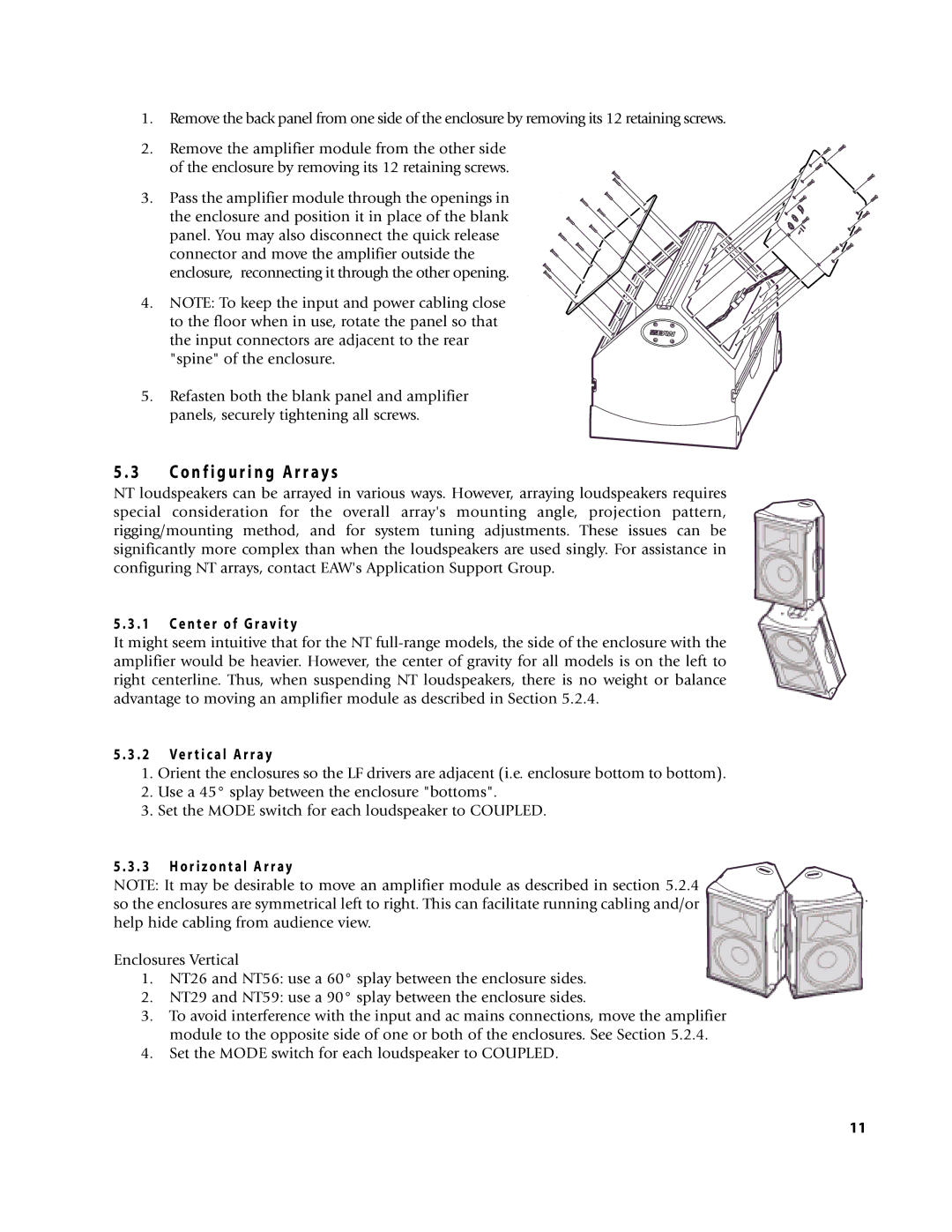
5 . 3 . 2 Ve r t i c a l A r r a y
1.Orient the enclosures so the LF drivers are adjacent (i.e. enclosure bottom to bottom).
2.Use a 45° splay between the enclosure "bottoms".
3.Set the MODE switch for each loudspeaker to COUPLED.
5 . 3 . 3 H o r i z o n t a l A r r a y
NOTE: It may be desirable to move an amplifier module as described in section 5.2.4 so the enclosures are symmetrical left to right. This can facilitate running cabling and/or help hide cabling from audience view.
Enclosures Vertical
1. NT26 and NT56: use a 60° splay between the enclosure sides.
2. NT29 and NT59: use a 90° splay between the enclosure sides.
3.To avoid interference with the input and ac mains connections, move the amplifier module to the opposite side of one or both of the enclosures. See Section 5.2.4.
4.Set the MODE switch for each loudspeaker to COUPLED.
11