Appendix
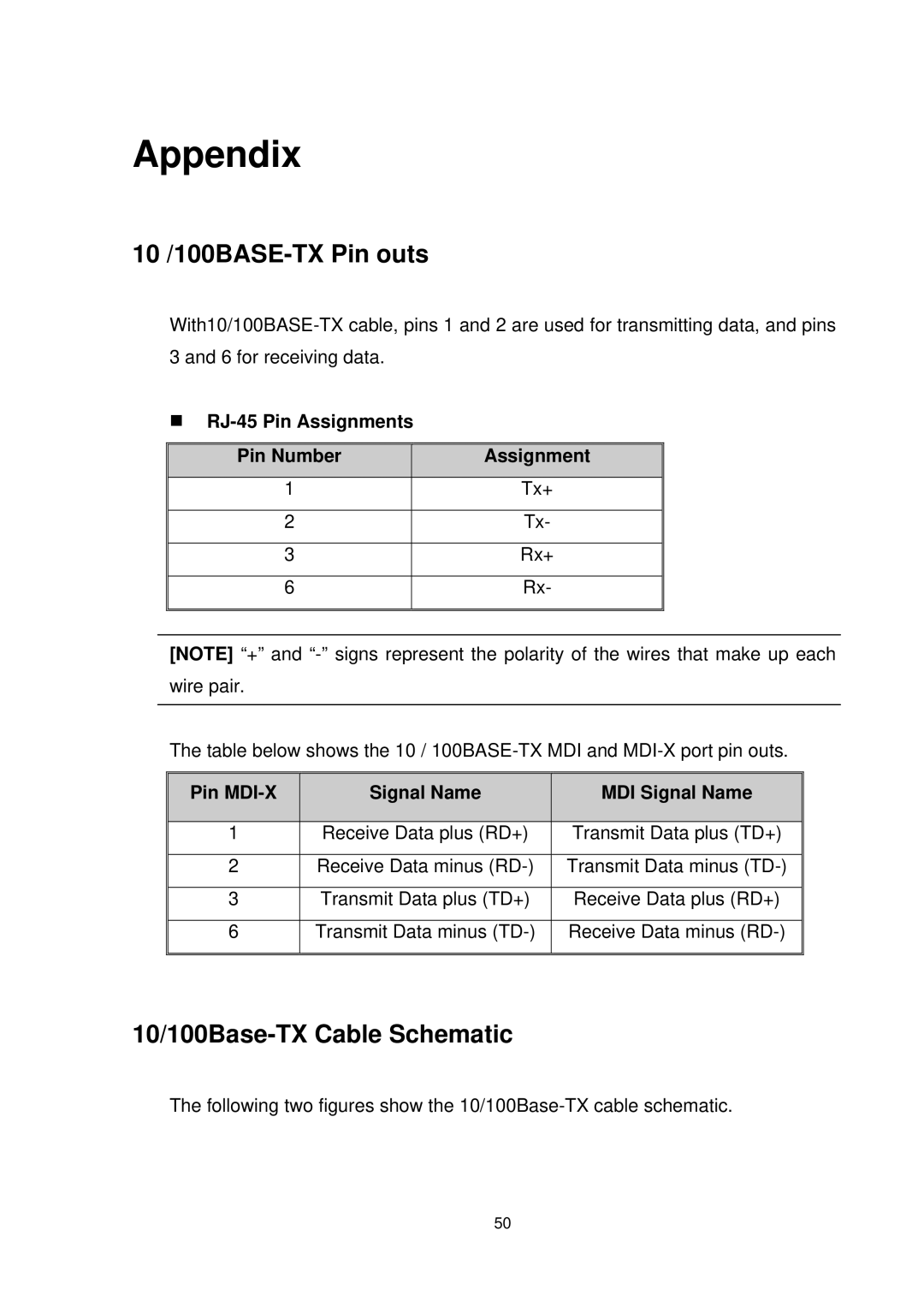
10 /100BASE-TX Pin outs
| Pin Number | Assignment |
|
|
|
|
|
| 1 | Tx+ |
|
|
|
|
|
| 2 | Tx- |
|
|
|
|
|
| 3 | Rx+ |
|
|
|
|
|
| 6 | Rx- |
|
|
|
|
|
|
|
|
|
[NOTE] “+” and
The table below shows the 10 /
Pin | Signal Name | MDI Signal Name |
|
|
|
1 | Receive Data plus (RD+) | Transmit Data plus (TD+) |
|
|
|
2 | Receive Data minus | Transmit Data minus |
|
|
|
3 | Transmit Data plus (TD+) | Receive Data plus (RD+) |
|
|
|
6 | Transmit Data minus | Receive Data minus |
|
|
|
10/100Base-TX Cable Schematic
The following two figures show the
50