1-3. Controls & Connectors
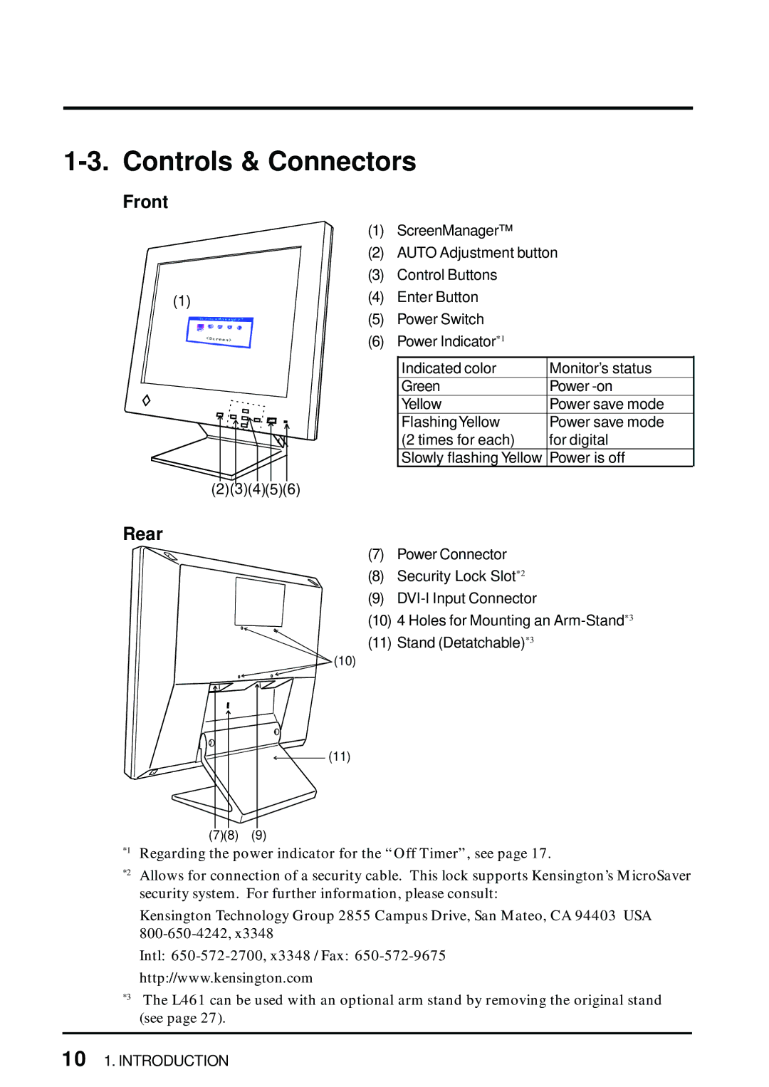
Front
| (1) | ScreenManager™ |
| (2) | AUTO Adjustment button |
| (3) | Control Buttons |
(1) | (4) | Enter Button |
(5)Power Switch
(6)Power Indicator*1
Indicated color | Monitor’s status |
Green | Power |
Yellow | Power save mode |
FlashingYellow | Power save mode |
(2 times for each) | for digital |
Slowly flashing Yellow | Power is off |
(2)(3)(4)(5)(6)
Rear
(7) Power Connector
(8) Security Lock Slot*2
(9)
(10) 4 Holes for Mounting an
(11) Stand (Detatchable)*3
![]() (10)
(10)
![]()
![]()
![]() (11)
(11)
(7)(8) (9)
*1 Regarding the power indicator for the “Off Timer”, see page 17.
*2 Allows for connection of a security cable. This lock supports Kensington’s MicroSaver security system. For further information, please consult:
Kensington Technology Group 2855 Campus Drive, San Mateo, CA 94403 USA
Intl:
http://www.kensington.com
*3 The L461 can be used with an optional arm stand by removing the original stand (see page 27).
10 1. INTRODUCTION