V883 INSTALLATION MANUAL | E L A N H O M E S Y S T E M S |
DIP Switch Settings - UNIT ID
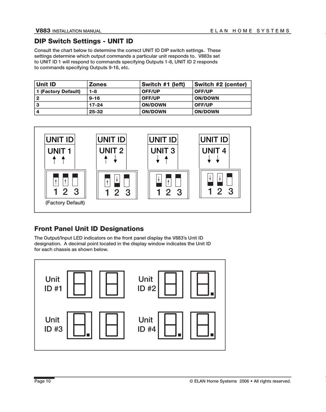
Consult the chart below to determine the correct UNIT ID DIP switch settings. These settings determine which output commands a particular unit responds to. V883s set to UNIT ID 1 will respond to commands specifying Outputs
Unit ID | Zones | Switch #1 (left) | Switch #2 (center) |
1 (Factory Default) | OFF/UP | OFF/UP | |
2 | OFF/UP | ON/DOWN | |
3 | ON/DOWN | OFF/UP | |
4 | ON/DOWN | ON/DOWN |
UNIT ID |
| UNIT ID |
| UNIT ID |
| UNIT ID |
|
UNIT 1 |
| UNIT 2 |
| UNIT 3 |
| UNIT 4 |
|
1 2 | 3 | 1 2 | 3 | 1 2 | 3 | 1 2 | 3 |
(Factory Default) |
|
|
|
|
|
| |
Front Panel Unit ID Designations
The Output/Input LED indicators on the front panel display the V883’s Unit ID designation. A decimal point located in the display window indicates the Unit ID for each chassis as shown below.
Unit | Unit |
ID #1 | ID #2 |
Unit | Unit |
ID #3 | ID #4 |
|
|
|
|
|
|
|
|
|
|
|
|
|
|
|
|
|
|
|
|
|
|
|
|
Page 10 |
|
|
| © ELAN Home Systems 2006 • All rights reserved. | |||