E L A N H O M E S Y S T E M S | V883 INSTALLATION MANUAL |
Control Connections - VIA!NET
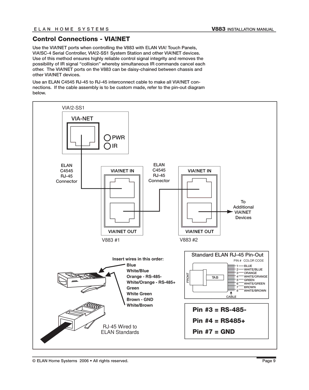
Use the VIA!NET ports when controlling the V883 with ELAN VIA! Touch Panels,
Use an ELAN C4545
VIA-NET
|
|
|
|
|
|
|
|
|
|
| PWR |
| ||||
|
|
|
|
|
|
|
|
|
|
|
| |||||
|
|
|
|
|
|
|
|
|
|
|
| |||||
|
|
|
|
|
|
|
|
|
|
| IR |
| ||||
|
|
|
|
|
|
|
|
|
|
|
| |||||
|
|
|
|
|
|
|
|
|
|
|
| |||||
|
|
|
|
|
|
|
|
|
|
|
|
|
|
| ||
ELAN |
|
|
|
|
|
|
|
|
| |||||||
|
|
|
|
|
|
|
|
|
|
|
| |||||
C4545 |
|
|
| VIA!NET IN |
| |||||||||||
|
|
|
|
|
|
|
|
| ||||||||
|
|
|
|
|
|
| ||||||||||
Connector |
|
|
|
|
|
|
|
|
| |||||||
|
|
|
|
|
|
| ||||||||||
|
|
|
|
|
|
|
|
|
|
|
|
|
|
|
|
|
|
|
|
|
|
|
|
|
|
|
|
|
|
|
|
|
|
|
|
|
|
|
|
|
|
|
|
|
|
|
|
|
|
|
|
|
|
|
|
|
|
|
|
|
|
|
|
|
|
|
|
ELAN
C4545
Connector
VIA!NET IN
To
Additional
![]() VIA!NET
VIA!NET
Devices
VIA!NET OUT
VIA!NET OUT
V883 #1 | V883 #2 |
Insert wires in this order: ![]() Blue
Blue
White/Blue Orange -
White Green
Brown - GND
White/Brown
RJ-45 Wired to
ELAN Standards
Standard ELAN RJ-45 Pin-Out
|
|
|
|
| PIN # | COLOR CODE | |
|
|
|
|
|
| 1 | BLUE |
|
|
|
|
|
| ||
|
|
|
|
|
| 2 | WHITE/BLUE |
FRONT |
|
|
|
|
| 3 | ORANGE |
|
| TAB |
|
| 4 | WHITE/ORANGE | |
|
|
|
|
|
| 5 | GREEN |
|
|
|
|
|
| ||
|
|
|
|
|
| 6 | WHITE/GREEN |
|
|
|
|
|
| 7 | BROWN |
|
|
|
|
|
| 8 | WHITE/BROWN |
|
|
|
|
|
| ||
CABLE
Pin #3 = RS-485-
Pin #4 = RS485+
Pin #7 = GND
© ELAN Home Systems 2006 • All rights reserved. | Page 9 |